Sovol SV08 Multiple Motion System Upgrade.
-
It moves......
Next step - wire up 3rd extruder with 1LC tool board.
Then some more end stops and homing.
-
Starting on wiring up the 1LC on the last extruder.
Horizontal placement of the board above the extruder is not that neat - but I guess the for left hand extruder the overlap isn't a big issue.
For the other two extruders I made up adaptors - to make the upgrade reversible - I think for this one I will take a different approach - and cut and replace the connectors on any cables that are long enough - as likely to have two spare extruders once I do the INDX upgrade even if I end up trying a Klipper version later.

-
@dwuk3d All wired up


-
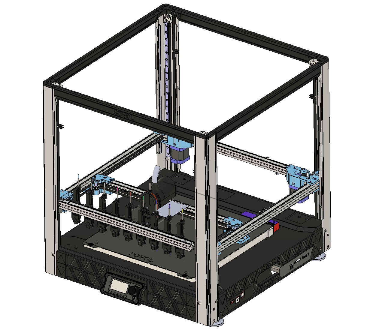
Updated my CAD for INDX a bit based on latest pictures, plus created a Voron Zero version.


-
Almost ready to start trying homing.
Decided to home the left extruder on the right extruder - mainly so that can use an identical design for two extruders.
So right extruder will need to be homed first on the gantry.
Also doubled up on end stops again - so single optical sensor left extruder for U axis (X) (homing on to other extruder) , D Zhopper, then another single optical sensor for right extruder - C axis (X) and A Zhopper.
Will probably have to rationalise the axis letters at some point.

Used an M4 bolt again for lead screw on left extruder as need to order some more lead screw nema 11s.
-
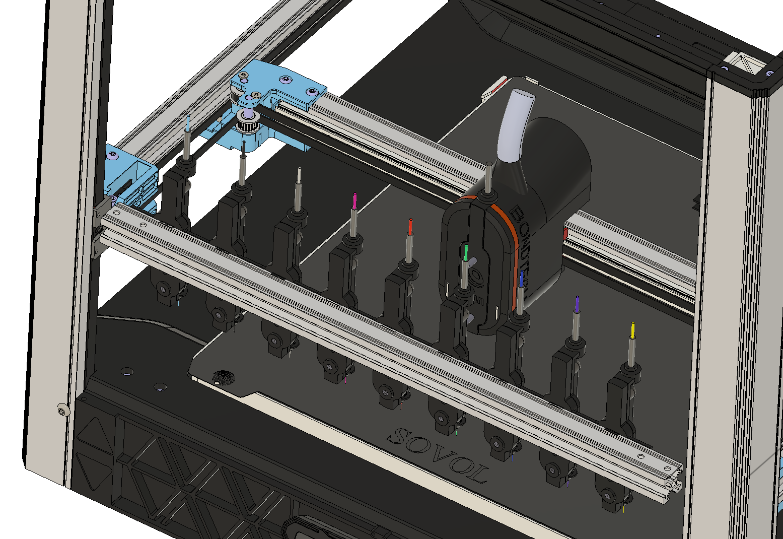
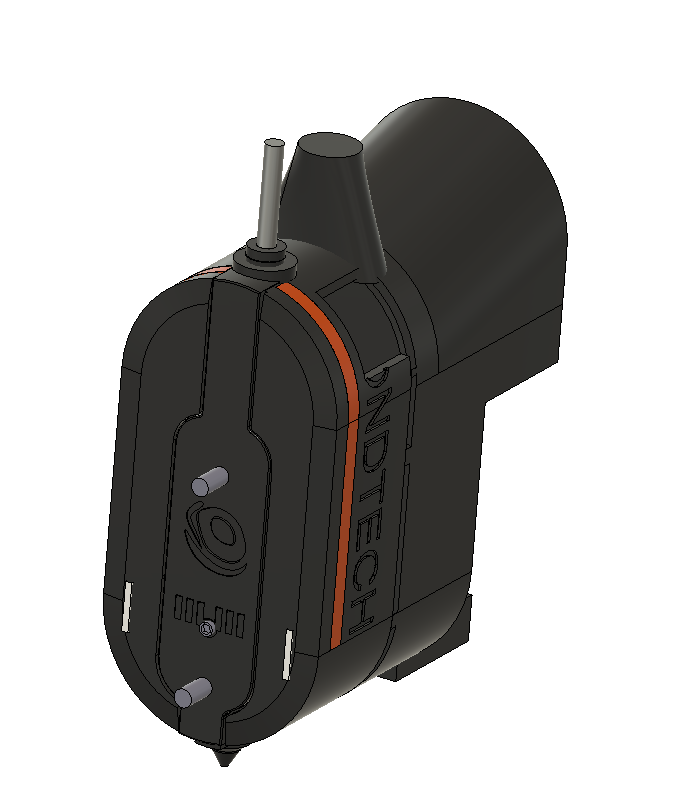
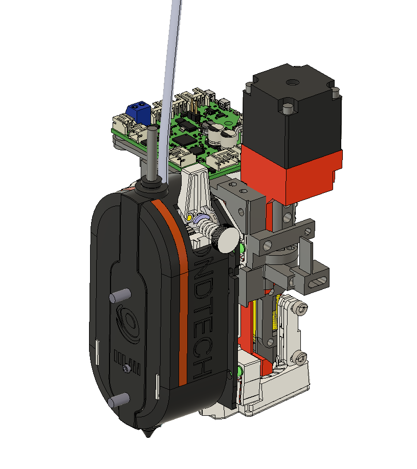
Rough scale of Bondtech INDX toolhead overlaid over my current SOVOL toolhead.


-
@dwuk3d The main negative I can see of the Bondtech INDX that I can see is that the nozzle is far forward, away from the X axis and carriage. This is understandable given the layout, but I think it will mean losing some Y axis, or mean that the bed will have to move towards the front of the printer for full coverage.
Ian
Bed-slinger - Mini5+ WiFi/1LC | RRP Fisher v1 - D2 WiFi | Polargraph - D2 WiFi | TronXY X5S - 6HC/Roto | CNC router - 6HC | Tractus3D T1250 - D2 Eth
-
@droftarts Your input just started a long train of thought, but it's not related to this thread.
[OT]
The almost forgotten screw-extruder was build as DD extruder (hollow shaft a.s.o.) but with a bit of modification it could become a super compact tool changer, similar to the INDX. Plus it wouldn't need hollow shaft motors anymore.(no filament softening issues! ) -
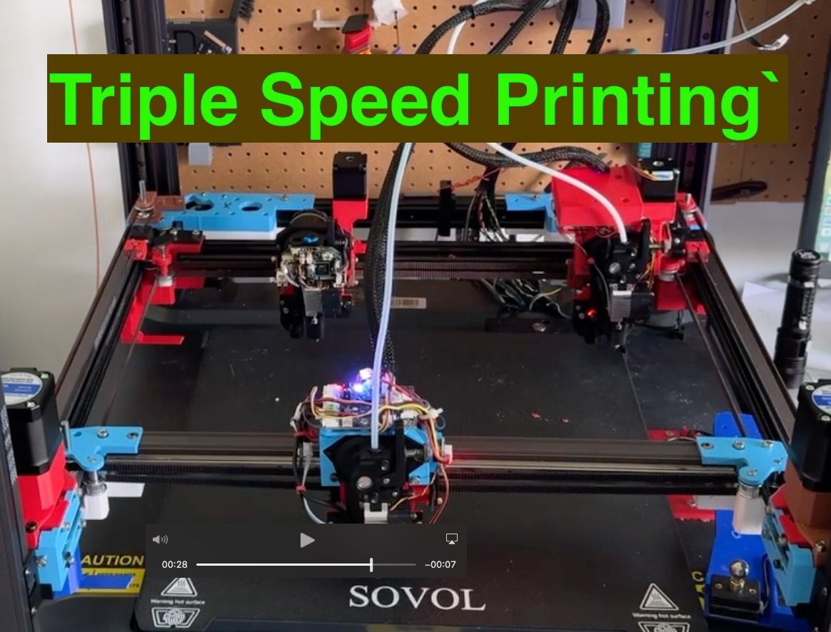
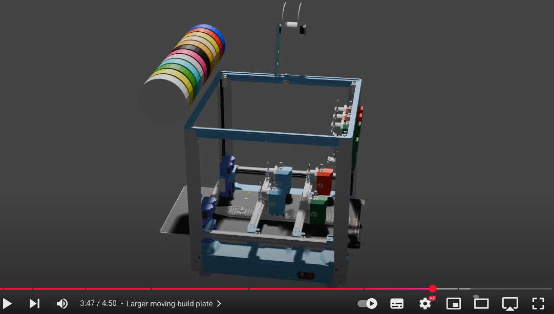
First proper three headed print.
Some work required on alignment, purging and speed - but quite pleased with results so far.
Gantry 1 and 2 are running on different motions systems - and very slightly in parallel.
https://youtu.be/4TYAep9QcUE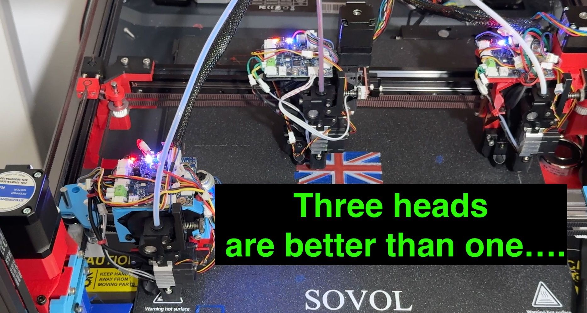
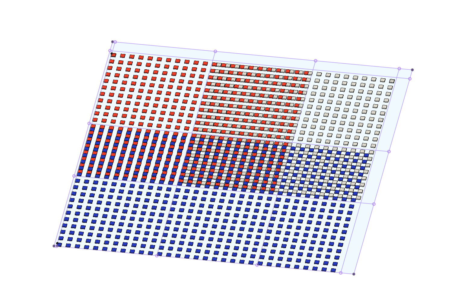
Three colour build area a little bit restricted - so need to get the print heads a little bit smaller...
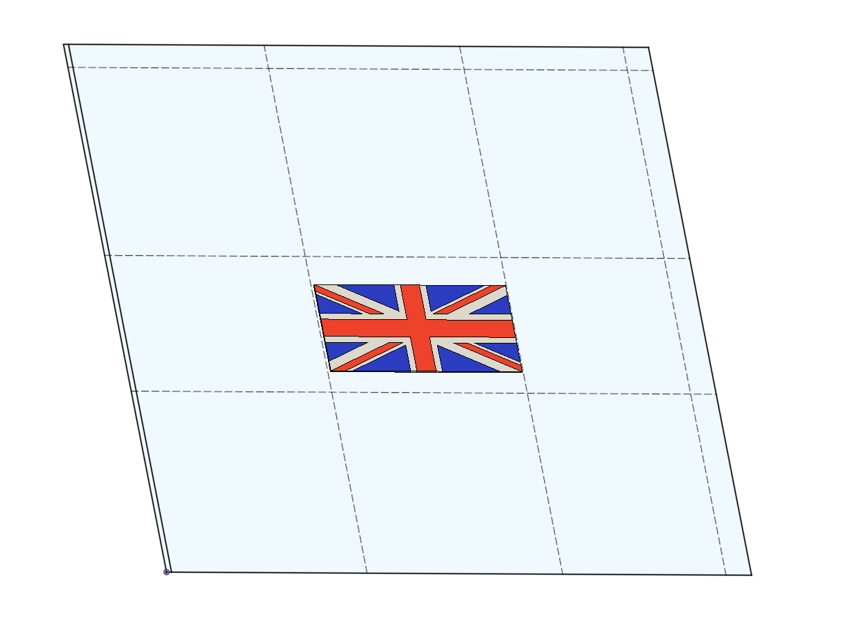
NB/ Flag on printer is 70% of this scale - so could print a slightly bigger one.Changed over C gantry to be W as missing out a letter caused problems with tools definitions.
Also put V motors on correct AxisKinematics now simply the following
M669 K1 ; configure CoreXY kinematics ; X:Y:Z: U: V: W:A:B:D M669 V0:0:0: 1: 1:-1:0:0:0 -
@dwuk3d said in Sovol SV08 Multiple Motion System Upgrade.:
Changed over C gantry to be W as missing out a letter caused problems with tools definitions.
Missing out a letter should not matter. What might matter is that in the M584 command that creates the axes, C default to rotary but W defaults to linear.
Duet WiFi hardware designer and firmware engineer
Please do not ask me for Duet support via PM or email, use the forum
http://www.escher3d.com, https://miscsolutions.wordpress.com -
@dc42 when I had the X axis on T2 as 7 - which was C, when I tried to move on the X axis it would move only in 0.1mm steps - and it went in the wrong direction.
If I tried to move in bigger increments it would stop.
Changing over to W not a big issue - I think it makes more sense having rear gantry as UVW - than UVC
I still have a gap between B & D - but doesn't seem to be causing any issues so far.
-
Thinking about getting full coverage of the bed for all print heads.
My current plan for the next phase is occasionally moving bed in the Y direction - like this
https://youtu.be/479ecxP-sOE?t=194
I'm now wondering whether to go straight to phase 6 - the rotating bed approach might work better for the next phase.
It doesn't even need to be infinitely rotating - as that would require slip rings etc for the wiring.Could for this phase just have it rotate 90, 180 , 270 degrees and back which the wiring should be able to handle - and I think that would mean the whole bed would be reachable by all 3 print heads.
Biggest challenge would be ideally carrying on printing while the rotation is happening, plus where to put the probe.
-
Awesome print video

I'd give it a like, but I don't watch YT while being logged in.
I've noticed, the red tool was pretty impatient priming and wiping the nozzle, while blue was still printing. I guess that's a matter of postprocessing.
Changing from red to white or vice versa is a different act, because they move on the same y-beam and the unused tool is up in the air.
Maybe you can lower it for wiping and raise it again until it's on duty?@dwuk3d said in Sovol SV08 Multiple Motion System Upgrade.:
My current plan for the next phase is occasionally moving bed in the Y direction
It's obvious how much print area you loose with the blue tool looking in the same direction...but for tool change-reasons you have to look for Plan B
You might not even need a bigger heater for the bed, since the print area is still the same.
PS: If you take the bed-slinger route anyway, why not reconstruct the gantry to move only in X-direction and let the bed do Y. Just like many Prusa I3 clones still do.
It'll save a ton of motors/belts/idlers on the gantryForget that, you want to print with 2 heads simultaneously later on, which is impossible with a bed slinger...
-
@o_lampe Thanks - yes some of the tools did start priming a bit early - I need to tweak my timing algorithm - its based on calculating the required delay within the 20 seconds preheat window, then just kicking off reheat and then prime as soon as heat up is complete. I should delay prime until the last few seconds. - also the 20 seconds pre-heat the slicer sends isn't always completely accurate - might just be a bug, or might be that I haven't got the printer completely configured exactly as its defined in the slicer in terms of speeds and accelerations.
I was really pleased though at how quick the tool changes are coming - will be even more apparent when I do prints with less of some of the colours per layer.
I have considered investigating simulations - but I might just try making the algorithm monitor itself and auto adjust - at least when it repeats the same print.
Yes I can't parallel prime when printing between the heads on the same gantry - and I do need to sort out some of the details - like lifting and lowering.
I will hopefully stay at this phase for a few months to get the parallel printing working really well, - especially with a combination of Independent and IDEX -
The beg slinger approach I am not sure about - it might be a step backwards - and does bring space issues - so might consider extending the whole frame - at least in the Y direction.
-
@dwuk3d As long as you don't go the rotating bed route, I'm sure you'll be succesful.
It has been proven (by @CNCmodeller ) that the accelerations required to print near the center of a rotating bed are impossible to achieve. The center itself is a No-Go zone. -
@o_lampe Can't find the @CNCModeller post - although I suspect you are talking about rotary printers - with the rotary motion is one of the Axis - and when you are right in the centre you need to speed the spinning up very fast to get the same amount of motion as you would get from the edge.
I'm not proposing that - I am still proposing a normal XY type AXIS - just having rotary as mainly a way of moving parts of the bed to different places within the print head envelope to allow better coverage / more parallel printing.
Continuous rotation would be nice too - to allow things like parallel vase mode prints.
-
@dwuk3d said in Sovol SV08 Multiple Motion System Upgrade.:
Can't find the @CNCModeller post
Hmm, me neither. Maybe he was so succesful with it, that he went closed source ?
I only found this early photo of polar printer
Parallel Vase mode would be cool, but when I made things in vase mode I already had to slow down a lot, because of the minimum layer time/part cooling.
With multiple heads you'd also have to sort out a precise method to sync layer times, unless the part is super symmetric. But with such a part, you can just split it in vertical halfes (or quarters) and use mirror mode on a stationary bed. -
@o_lampe yes you are right about needing to sync layer times.
I will probably do something symmetrical like a sphere first - but to really demonstrate the concept I want to do a really complex non symmetrical shape, with layer times syncronised by slowing down some of the heads at appropriate times.
Will want to do this on normal segmented parallel prints too - to avoid heads going idle and needing to be cooled down, parked, primed and reheated as much as possible,
One of my earlier youtube shorts demonstrated the multi head vase mode principle.
Also Nathan Builds Robots massive printer does something like I want to do - although his design is restricted to only having in and out and up and down on each head - so would suffer from the 'centre' speed issues you mention.
-
Made a bit of progress on alignment issues - i think its a dimensional accuracy issue - and may actually be a problem with my Dual Markforged kinematics when moving in the X and Y direction at the same time.
Or might be due to the backlash compensation I put on the old V axis - which is now the X axis (W) on my third toolhead - which is the one that seems to be squashing up its dimensions a little bit when compared to the other print heads.
i need to take a break from this printer for a few days - so will address the issue later,
One big discovery I did make though while trying to resolve this - is that what I previously thought were strange hangs on things like M598's, M400's or M596's - which led me to completely stop using M598's were probably more like the fact that echo commands sometimes seem to stop working on forked multiple motion systems.
I put in loads of echo's before and after commands thinking I could see where control on each file was hanging - but worked out today that processing was actually still running in loops and commands quite a long way further into the file - usually on G4 500's in loops.
When this happen's M122 still seems to tell you the G4 or other command each file is currently on - so I have changed every G4 to have a slightly different millisecond delay time value - so that it is then possible from the M122 to work out which delay loop each forked file is currently executing.
Might start using global variables to trace current position - rather than echo's to see if that works more reliably.
Nb/ I am still on 3.5.4 - will test out some of this on 3.6 at some point too.
-
Another issue I have is with the probe moving a bit - I've changed a few things - but it is still not perfect. I have been considering changing from using a servo to a stepper - I think a fairly big Nema17 might hold the probe more steady in the Y direction or I could try a Nema23. The magnet is probably better at holding it in place in the Z direction. I might try also trying so somehow interlock something into the indentation of the magnet when it pulls down - to also prevent Y movement.
Re rotary bed
The next challenge after that is bed coverage by each print head.My current thinking is once per layer rotate the bed 90, 180 and 270 degrees. - I will be rotating a square rather than round bed.
That should allow all 3 heads to access the whole bed, plus allow parallel printing.
If i only rotate it like that and then rotate it back again then I won't have any wiring issues - but I would also like to try making in continuously rotate capable like yours - so that I can do 3 headed vase mode prints.
I think i will need a 4 way slip ring for this capable of mains power - any thoughts on this.
I suppose I could go 2 way - just for the bed heater - and try using something like an IR temperature sensor for temperature - but not sure whether the PWM or whatever stuff would handle that.
