CoreXYUVWA - 3rd gantry homing SOLVED
-
@wilriker said in CoreXYUVWA:
@deckingman I think it will not need new kinematics but I might be wrong on that. AFAIK you can add additional axes to every kinematic just by defining them. And to why that might be sufficient:
I also think it would be easier to have all the inversions only logically i.e. you tell the firmware that the motor runs forward when in reality it runs backward. You tell the firmware to home to W/A min when in reality you have the endstop at max (relative to XYUV min/max). This way you could still home them separately and combine them just as you do with X+U and Y+V. It would then just be X+U+W and Y+V+A after homing. Then XYUV would run forward and WA backward without the firmware having to care.
@dc42 In case it does need some new kinematics and you basically approve it I am volunteering to work with Ian on this and take over the RRF part.
Yes, that's the way I intended to do the inversions. When I had just CoreXY then added UV, David had to create a new Kinematics for me to be able to home UV independently of XY (M669 K8 is CoreXYUV). If you look at M669, the K parameter is a single digit. 0 to 8 are already taken and 9 is reserved so it may not be possible.
It would be nice to have but it's not a huge problem if it's not possible. I can simply map the additional drives to the existing XY and build in a mechanical clutch on the motors, or some such thing, to prevent damage in case of crashing into the bed frame. Or just be careful to manually align this additional gantry with the lower ones.
-
@deckingman said in CoreXYUVWA:
When I had just CoreXY then added UV, David had to create a new Kinematics for me to be able to home UV independently of XY
Ok, did not know that dependency.
If you look at M669, the K parameter is a single digit. 0 to 8 are already taken and 9 is reserved so it may not be possible.
Don't worry this is not limited to single digits.
") I just checked the source code that handles
I just checked the source code that handles M669. -
@wilriker OK. We'll wait and see what DC has to say. I expect he's really busy with the upcoming TCT show. No hurry - I haven't even begun to design the hardware modifications yet. The trouble is, the filament spools sit at the very top of the printer so this additional gantry will have to be above them. That means it'll be over 1.8 metres above the floor. I'm only about 1.75 metres tall so it'll be above head height and I'll need to stand on a step to work on it

-
@deckingman Hehe, also taller than me then because I am about your height.

-
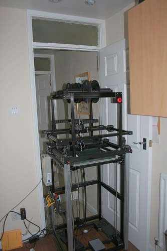
The filament spools now sit a little higher than shown below so I'll need to be careful that the printer will fit through the door when I add the extra gantry. No wait - if I want to take it anywhere, I have to take the top section off in any case because to UV axis is wider than the door. Not that I move it often......
-
You could go pure mechanical and strap a passive counterweight onto each part of the gantry using simple Cartesian X and Y belts. Make a simple belt loop, tie one side to the CoreXY carriage, then attach a mass to the other side of the carriage on a secondary rod. (8mm rod is fine to just carry a counterweight.)
I’ve been seriously considering this for future high-speed builds but it’s a better fit for an XY Cartesian or Ultimaker gantry than CoreXY.
-
@rcarlyle Yes thought of that too. In fact, that's how I started out driving the extruder gantry. It wasn't ideal for a number of reasons. Given that the total mass that is moved in Y is around 3 Kg, I'd likely need to add another 2Kg to the upper gantry. Although it's moving in the opposite directions, it's still mass that has to be moved and more importantly accelerated. So it's extra load on the motors, which are close to their limits. Also because there is no active breaking of the passive gantry,you need a very rigid connection between the driven gantry and the passive one which has a tendency to lag behind at the start of a move, then overshoot at the end. Having tried both, I favour the driven approach.
I looked at using a Tuned Mass Damper (essentially a lump of mass on a damped pendulum) but they have to be tuned to a specific frequency or frequencies so won't work over the speed range that we use with printers. Difficult to do in both X and Y direction too. Might be possible, but it's a lot more complicated than would seem at first glance. -
@deckingman I am not sure the counterweight is the best approach. I built a similar construction with extrusions 1.5 m high. My construction was were stiff at the top, but at the bottom lightweight like in your picture. The construction oscillated very much. IMHO the reason for swinging lies in the bottom. Making it more stiff in the bottom will be more advantagous for getting stability than adding weight at the top. You can even think of adding a modular, removable component at the bottom which can be removed easily for transport.
(Even easier: fixing the middle part at the wall...)
An inexpensive solution would be a cage made from concreate around the printer, opened at one side only. The concrete dampens vibrations.
-
@joergs5 For sure adding mass to the bottom helps with overall stability. Better still would be a large block of concrete or some such, connected to the fame via friction dampers (shock absorbers), a bit like front load washing machines. That's not an option in my case. The issue is that the floor itself has some flex in it because it's laminate on top of fibre board insulation, one top of chipboard, on top of timber joists. Spreading the foot load would work better than adding mas but that isn't an option either. Adding mass to the bottom doesn't help with any flexing of the frame either. And no matter how stiff the frame, there will be some flexing when accelerating and decelerating a large mass. Applying a dynamic opposing force will work better IMO.
Also for sure, screwing it to a wall would be the simplest solution but where is the fun in that?
-
@deckingman I wanted to give you some options only. I am sure building a third level is more fun than simply using conrete
") I thought about anti-vibration methods also. One possibility would be to compensate e. g. stepper vibrations by anti-vibrations etc. I wish you success.
I thought about anti-vibration methods also. One possibility would be to compensate e. g. stepper vibrations by anti-vibrations etc. I wish you success.The laminate argument is interesting. I am building a CNC machine and think about whether a concrete socket makes sense or not. I have laminate also, so a socket instead of the laminate may be better.
-
@deckingman I had one more idea: in robotics or helicopters one wants to balance out by counter movements. This is similar to your problem, where you want to even out a movement (the vibration). So a different approach is installing sensors (gyro) which analyze the vibrations and use your counterweights to diminish them. This would solve the problem that you can react to time delays which may occur, also.
-
@joergs5 If you can, then definitely install the machine on a sound base - concrete would be ideal. I can't do that with mine because it sits in an upstairs bedroom.
I don't see the point of adding a gyro to analyse the vibrations. It's an added layer of complexity to what is essentially a simple problem. Its just a matter of applying an equal and opposite force so that one cancels out the other. So a gantry moving a mass at the same speed and acceleration but in the opposite direction is all that's required.
As the cancelling mass will be higher than the print head and extruder mass then there will be a leverage effect, so the only tuning will be to find the correct mass needed. This is easily done. I can measure the deflection at the top of the printer with a dial gauge, then gradually add mass while running the print head and extruders back and forth at high speed/high accelerations until the deflection is zero. I plan to use lead shot for the mass.
Most of the mechanical design is now done and I'll start printing parts and ordering motors and aluminium extrusion. It's a simplified CoreXY gantry with a single X rail. The X carriage is a hollow cuboid into which I can add the lead shot. I'm not too worried about the gantry sagging or really precise positional accuracy - it's just a lump of mass being moved around so as long as it's free to move and travel the correct distance, that's all that is required.
I did consider using axis that were half the length, doubling the mass and halving the steps per mm for those motors. It would be more compact, but it's hard to fit without a fairly major re-design of the printer.
I'll need some help getting the two additional external stepper drivers interfaced but @wilriker has said he can help me with that.
I'll do a write up on my blog when it's all done and report the findings (good or bad).
-
The concrete socket is at the optimal timing, as I installed an underfloor heating in the workshop and not finished the laminate yet. I will do it this way, adding a socket for the 3d printer also.
I am curious how your project is going!
P.S. vibrations can cause a fall (unexpected ones!), so please attach a security rope at the ceiling.
-
@dc42 I looked into the
CoreXYUVKinematics.(h|cpp)and it will be easy to extend/copy-paste this to CoreXYUVWA (I will also add CoreXYUVW if you think it makes sense).I found something in your
BugList.txtthat is very relevant to thisM569 command to allow selection of smart/dumb driver [...] also allow all 12 drivers to be smart
Can you tell me more about that especially the second half? What do you plan there? And what needs to be done? Did you think about TMC2660-BOB when writing this? If that is not to be more public you can of course email me. I can keep secrets.
-
@deckingman can you fill me in on why you need separate controlled axes and not just run multiple drivers off the same step/dir signals? I know stall-homing isn’t great for CoreXY, so why not just manually position the axes where they are supposed to go at startup, home CoreXY with switches like normal, and rely on dead reckoning for the secondary and tertiary gantries?
-
@rcarlyle said in CoreXYUVWA:
@deckingman can you fill me in on why you need separate controlled axes and not just run multiple drivers off the same step/dir signals? I know stall-homing isn’t great for CoreXY, so why not just manually position the axes where they are supposed to go at startup, home CoreXY with switches like normal, and rely on dead reckoning for the secondary and tertiary gantries?
That's what I'll likely end up doing with this third gantry. It's how I started out with the second one too. But when I was working on the machine or just changing filament, I had a habit of inadvertently nudging the extruder gantry and forgetting to line it up again by eye before I did the homing. So I had quite few crashes which became a bit tiresome. I always drop the motor current when homing so it didn't do any damage but it was annoying. I posted the issue on these forums and David kindly implemented CoreXYUV kinematics for the purpose of homing. Now I don't have to worry about knocking one gantry out of alignment with the other.
What happens is that the motors are mapped to XY and UV for homing. Then once homing is completed fr all 4 axes, both pairs of motors are re-mapped to X and Y, and U and V are hidden. So, for printing it's just like a CoreXY which happens to have 2 alpha motors and 2 beta motors.
There is no problem mapping the third gantry motors to X and Y but in this case, I'd just reverse the motor directions in config.g so that the axes do the opposite thing. If I could also home this third gantry independently, it would be nice but it's not a huge issue. It'll work but I'll just have to remember to "eye ball" it before I start the homing sequence. Or as I've said previously, I can build some "slippage" into the system.
I summary, it doesn't need to be CoreXYUVWA to work, but it would be nice if it was possible.
-
Ian, you could show a popup when homing, and wait for user (you) to put the gantry in the correct position, then click OK...
-
@fma Yes I know. there are all sorts of work arounds and things that I can do.
@all
Sorry if his seems blunt or harsh but getting back to my original post, and the reason I started this thread, all I want to know is would it possible to home an additional WA gantry, given that I currently use CoreXYUV? Or if it isn't currently possible, then could it be possible?
If the answer to that is no, then that's fine. If the answer is yes, then what do I need to do?
-
OK, So I think I've figured out a way to home all these axes and gantries without needing any changes to firmware but I need DC42s input when he gets time (no hurry).
To save any confusion, on a Corexy, both X and Y motors contribute to motion so it's better to all them Alpha and Beta.
At the moment, the XY part of the CoreXY has two alpha motors and 2 beta motors for normal printing. Axes U and V are for homing only and are otherwise hidden. When homing, one Alpha motor and 1 Beta motor are assigned to the XY axes and the second Alpha and Beta motors are re-assigned to UV.
The idea I have is to add the third pair of motors to XY for normal printing, so there would be 3 Alpha motors and 3 Beta motors (instead of 2). I would home XYUV as I do now. Then I could map the third pair of motors to UV (instead of the second pair), re-assign the end stop switches for the third gantry to UV, then repeat XYUV homing (but this time it would do gantries 1 and 3 instead of gantries 1 and 2). Finally assign the end stop switches back to the default UV gantry, re-assign all 3 alpha and beta motors back to XY. This would all take place within the homing macros for homex, homey and homeall.
It's a bit complex but I think it would work. Have I missed anything?
In config.g M584 is currently X0:3 Y1:4 Z2 U10 V11 E5:6:7:8:9. This would need to change to something like M584 X0:3:10 Y1:4:11 Z2 E5:6:7:8:9 U12:13 V14:15 or some such.
Then for homing first pass it would be as now i.e M584 X0 U3 Y1 V4 P5
For homing second pass (the 3rd gantry) they get re-mapped to
M584 X0 U10 Y1 V11 P5Then at the end of homing, they get mapped back to where we started.
Need your input David (DC42) - I appreciate you are busy getting ready for the TCT show etc, so as and when......
-
@deckingman I am not David but basically it might work like this except for a small hiccup in your second
M584definitionM584 X0:3:10 Y1:4:11 Z2 E5:6:7:8:9 U12:13 V14:15
because there you assign 16 drivers to all axes. It probably would rather look like
M584 X0:3:5 Y1:4:6 Z2 E7:8:9:10:11 U3:5 V4:6Note that I remapped some of your drivers here on purpose because I just stumbled across something that might be a problem. Documentation of
M584statesOn the Duet WiFi and Duet Ethernet, if you configure multiple drivers for an axis, either all of them must be TMC2660 drivers on the Duet or a Duet expansion board, or none of them must be. This is to facilitate dynamic microstepping and other features of the TMC2660.
I don't know if
Ecounts as an axis here. If so this won't be possible until the aforementioned plan to make all 12 drivers "smart" has been completed.