Duet3D Logo Duet3D
    • Tags
    • Documentation
    • Order
    • Register
    • Login
    1. Home
    2. RCarlyle
    • Profile
    • Following 0
    • Followers 0
    • Topics 11
    • Posts 203
    • Best 36
    • Controversial 0
    • Groups 0

    RCarlyle

    @RCarlyle

    53
    Reputation
    27
    Profile views
    203
    Posts
    0
    Followers
    0
    Following
    Joined Last Online

    RCarlyle Unfollow Follow

    Best posts made by RCarlyle

    • RE: Setting motor current higher than rated current?

      Ok, back up, there’s some bad info here.

      Typical NEMA 17 hybrid steppers used in 3D printers use “class B” insulation in the coils, which is rated to 130C. At this temperature, the motor should last on the order of >10,000 hours before failing. Every 10C you exceed the coil rating can be VERY LOOSELY APPROXIMATED to reduce the motor life in half. So at 160C coil temp the motor may only last ~1000 hours which is less than printers are generally expected to last. (This is not guaranteed and you should not base any plans on this.)

      The motor’s rated current ultimately comes from the 130C coil temp rating value and some assumptions about the motor’s ability to shed heat:

      • Standard -10C safety factor (run coils at 120C actual)
      • Ambient temperature is 50C
      • Motor is horizontal and open to free air convection on five sides
      • Driver doesn’t do anything screwy that causes excessive heating due to excessive high-frequency switching

      What happens in this scenario is that the coils heat up to 120C, and shed heat to the stator/housing, so the stator heats up to perhaps 80-90C, and then sheds heat to the 50C air. Heat flows from hotter to colder so these temperature deltas are required to cool the motor.

      To be clear: under these conditions, the motor run at rated current will last a loooong time. You don’t need to run it at 60-90% of rated current for the motor’s sake. That is done to protect fingers and plastic mounting hardware.

      At 71% of rated current, the motor’s temp rise above ambient will be half.
      At 141% of rated current, the motor’s temp rise above ambient will be double.

      For standard motor conditions, the coil temp rise is 120-50=70C. That much temperature delta is required to drive heat-shedding to the environment and reach equilibrium.

      If you cool the motor more aggressively, such as attaching fans or heatsinks or watercooling blocks, you can safely run higher than rated current.

      If your ambient temp is less than 50C, you can safely run higher than rated current.

      So, what’s a safe motor current? Depends on your setup. 110% is often going to be completely fine. 140% will definitely fry the coils if you don’t provide aggressive motor cooling.

      Say you want to run the motor in 30C air with a heatsink glued on and you’re willing to add some risk of premature failure. Maybe here we can tolerate 105C of coil temperature rise above ambient versus the design temp rise of 70C above ambient. That means you get 50% more temp delta and thus 50% more heat shedding. So the coils can be run at sqrt(1.5)=122% rated current. The motor will be way too hot to touch, but in theory, it will perform fine at that temp.

      Rotor demagnetization really isn’t much of an issue. Hybrid steppers run fine with weak permanent magnets. The magnet isn’t producing torque, it’s just steering the electromagnetic flux produced by the coils through the motor so it spins in a consistent direction.
      posted in Duet Hardware and wiring
      RCarlyleundefined
      RCarlyle
    • Just launched pre-orders of my 3D printing book

      [One-time plug, thanks mods]

      After years of work, my 3D Printing book is finally in press!
      3D Printer Engineering Volume 1: Motion Platform Design
      You can pre-order here for 15% off early-bird discount: http://www.sublimepublications.com/

      This is a book for anyone who designs, modifies, or maintains 3D printers. Which is everyone here, I think!

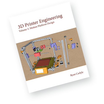
      front cover

      The first round of printing is supposed to be done in 1-2 weeks, so it will ship soon. The early bird discount is planned to end at that point.

      Table of contents for Volume 1:

      • Foreword (it opens with a quote from Jetguy, because hell yeah it does!)
      1. Introduction
      2. Machine Architectures
      3. Popular Machine Architectures
      4. Frame Construction
      5. Popular Frame Types
      6. Motion Hardware
      7. Popular Motion Systems
      • Closing
      • Further Reading

      Some of y'all already know this, but yes, this is the first book in a whole series of 3-5 or more books. Volume 2 (Drivetrains) and Volume 3 (Stepper Motors) are fully written, but need illustrating and editing, and that takes a healthy while. So I think Volume 2 is maybe a year out. (I wouldn't wait on more volumes to come out before you buy; I wrote Vol 1 to be a good resource on its own.)

      Electronics are planned for Volume 5, sorry that's going to be a good while out 🙂

      I'll post one more time when shipping starts, and then stop spamming y'all. Thanks to everyone here for years of interesting posts and discussions -- you were part of developing this book!

      posted in 3D Printing General Chat
      RCarlyleundefined
      RCarlyle
    • RE: coverting 3d printer to a laserengraver

      Obligatory safety note: strapping a laser onto a 3d printer creates SERIOUS SAFETY CONCERNS and the majority of people who do it don't follow enough safety precautions and are putting themselves at risk of fires and injury. I won't get into a full rant here, but some key guidelines to keep in mind:

      • Lasers over 0.5w can blind you instantly, and even reflections and dispersed laser flare off objects you're cutting can cause injury and fire. Blue diode lasers use a wavelength of light that can cause melanomas from skin contact in addition to burns. USE A FULL ENCLOSURE AND WEAR LASER SAFETY GOGGLES SUITABLE FOR ABSORBING YOUR CHOSEN LASER WAVELENGTH.
      • Do not put a laser on a machine made of flammable materials. (ABS, PLA, acrylic, wood, etc.)
      • Do not use fasteners that may vibrate loose and dislodge the laser mount.
      • Laser cutters/etchers produce toxic fumes and smoke that should be ventilated outside. Generally you will want to blast the cut with air to carry away vaporized material and smoke so the workpiece doesn't ignite, and then suck that air away to vent it outside.
      • If children, guests, or curious animals have access to the machine, make sure you put a key interlock or host computer password on it to prevent unauthorized laser activation.
      • Make sure you have an E-stop button or a power cable/switch within arm's reach of the front of the machine.
      • An enclosure cover interlock switch to inhibit unprotected laser fire is a REALLY good idea.
      • A laser power supply kill circuit to shut off the +v supply to the laser on ground-switched devices (like Duet heater MOSFETs) in case of component failure sticking the laser on is a REALLY good idea.
      • A smoke detector that shuts off machine power is a REALLY good idea.

      Some of the items above are actually US/EU regulations for laser devices, and you will be in deep doo if you burn down your house or hurt somebody and the insurance company starts investigating.

      posted in General Discussion
      RCarlyleundefined
      RCarlyle
    • RE: Pressure Advance Calibration

      I'm confused by how y'all are trying to use this script / tuning technique. Are people trying to use pressure advance to eliminate the difference in extrusion flow between 100mm/s and 5mm/s? That should be done with non-linear extrusion, not pressure advance.

      All hot ends extrude relatively less material (deviate from linearity between E axis travel and extruded filament volume) as the flow rate starts to approach the hot end's extrusion limit. This limit is largely a function of the nozzle size, and of the hot end's ability to transfer heat to the filament:

      1. PTFE-lined hot ends allow less heat flux and thus deviate from linearity at lower flow rates / print speeds. Insufficient heat flux = cooler extrusion = more viscosity.
      2. Higher extrusion rate = shorter residence time in the hot zone = less time for heat to transfer = cooler extrusion = more viscosity.
      3. Higher flow rate = more pressure drop at the nozzle.
        etc.

      There's a flow range where extrusion is very close to linear, and once you break out of that range, flow starts to deviate a lot. Basically as the back-pressure at the nozzle gets higher, the compressive force at the extruder gets higher, and the extruder drive loses travel because the hob bites squeeze closer together.

      So, it's totally expected that the hot end will extrude less material at a very high print speed, and you SHOULD see differences at 100mm/s vs 5mm/s. That's why the non-linear extrusion feature was made -- to offset that.

      Hot ends ALSO also have time lag / afterflow issues that specifically cause blobbing at corners, which is a largely unrelated issue. Flow lag is a transient effect that is only visible close to the speed change. This is primarily a matter of cumulative elasticity or "wind up" of all the components between the extruder motor and the nozzle:

      • Torque/error response of the stepper motor
      • Elastic shear of the drive hob bite zone
      • Compression of the filament between the drive hob and melt pool
      • Stretch of the bowden tube
      • Bulk compression of the melt pool
        (There there's more but I don't want to get into it right now.)

      All this elasticity means the extruder system has to "wind up" when it starts extruding to build up full extrusion force (effectively losing some filament volume), and then has to "unwind" when it stops extruding (getting the lost filament volume back as afterflow). Pressure advance is supposed to compensate for that.

      posted in Tuning and tweaking
      RCarlyleundefined
      RCarlyle
    • RE: PT100 vs Thermocouple Duet Daughter Boards

      Thermocouples are great, simple, and robust if you obey a few simple “gotcha” rules...

      1. No TC wire splicing unless you use more type-K TC wire and proper type-K plugs. The TC doesn’t actually measure tip temperature, it measures the difference in temperature from one end of the wire pair to the other. So the TC wire needs to run all the way to the Duet. There ARE plugs and extension wires available but you CANNOT use copper.
      2. Avoid running TC wires parallel to EM noise sources like untwisted motor or heater wiring. (This is good practice with thermistors and PT sensors too.)
      3. If the temp reads negative, flip the leads.
      4. One type-K wire is magnetic and one is not. This helps splice and terminate TC wire when the insulation color coding is inconsistent. (Different countries use different color standards.)
      5. Keep the tip electrically insulated from the hot block.
      6. Be careful of wire fatigue.

      The great thing about TCs in my view is that they’re just two-conductor wire with the tips touching... you can cut a thermocouple in half, strip and twist the tips, and now you have two thermocouples. It’s guaranteed to work and sense within about 2C accuracy by the metallurgy of the wires. There’s no magical and opaque at the tip that you have to worry about.

      posted in General Discussion
      RCarlyleundefined
      RCarlyle
    • RE: Homing Z in full steps

      @wilriker bipolar two-phase steppers have 50 rotor teeth and four distinct places those teeth can line up with the stator poles. That's how you get to 200 steps per rev. (400 steps/rev motors have 100 teeth instead.) So there are four full step positions for each rotor tooth and the microstepping sequence repeats four times before it starts over for the next rotor tooth. So with 1/16th microstepping there's actually 64 distinct microstep angles with different +/- signs for the coil energization. When you do more than four full steps, that sequence repeats.

      When you stop the motor, it can stop anywhere in the four step range. But when you power-on enable the driver, it will ALWAYS energize to a particular microstep in that four step range. The motor will jump to the power-on position from wherever it stopped. That means it pulls to the nearest rotor tooth, which can be up to 2 full steps away from the current location. (Half of the four-step sequence.)

      posted in Tuning and tweaking
      RCarlyleundefined
      RCarlyle
    • RE: Carbon Fiber pultruded tubes for X axis on Cartesian

      @briskspirit tubes will usually perform better than rods in this application since all meaningful loading is transverse/bending. The center of the rod lies on the neutral axis for bending, so it contributes minimal bending strength. In other words, tubes are lighter with nearly the same bending strength. This goes for steel and CF, but hollow linear rods are too expensive to be worth using from what I've seen. CF tubes are reasonably cost effective if you use CF.

      The problem is the modulus of elasticity or stiffness of the material per unit cross sectional area. If you have a fixed rod diameter or area (eg 8mm OD requirement) and a heavy carriage, then you'll get the highest performance from the material with the highest modulus of elasticity. Stiffness/weight ratio won't dominate, since we have a fixed amount of diameter to work with. Steel beats CF for that. It's when you can move to a larger tube diameter that CF beats steel.

      If the carriage is very light and the weight of the rods themselves dominates the moving mass, it's more complex and you really need to do some math to find which is better.

      posted in General Discussion
      RCarlyleundefined
      RCarlyle
    • RE: Motors running hot, but half the power & speed

      @cvmichael I am 100% positive you were never getting 50,000mm/min with Smoothieware and that hardware setup. Some firmware limit was keeping you way below that speed. Might have been a cap on step pulse frequency, or a queue depth limit (since Smoothie never exceeds a speed it can decelerate to 0 from during an E-stop), or some other setting.

      0.9 degree steppers wired in series on 12v absolutely cannot run fast. Each motor is only getting effectively 6v when you do that. There is not enough voltage being applied to each coil to overcome inductance and back-emf at high speeds.

      On the microstepping note, you never LOSE torque by using finer microstepping. Microstepping can only help until you go so fast you hit a firmware step pulse generation frequency limit. This is a commonly misunderstood issue. It's true that each individual microstep provides less torque with finer microstepping, but at the same time you take proportionately more microsteps, and the torque is additive, so finer microstepping ends up being the same running performance for the motor.

      A quick rule of thumb:

      • Full-stepping:: never do this, you will get mechanical resonance and lose lots of torque due to torque ripple
      • Half-stepping: barely acceptable if you're using a very high gear ratio and you can't generate enough step pulses any other way... still somewhat prone to resonance
      • Quarter-stepping: Basically the minimum you should try to use; this is where mechanical resonance instability largely drops off. Fine for geared extruders
      • 1/8-stepping: Noticeably better than 1/4 stepping in every way: quieter, smoother, finer motion resolution
      • 1/16-stepping: A little better than 1/8 stepping in every way. This is the point where motor angle errors are likely around the same magnitude as your microstep size, and so is a pretty reasonable stopping point
      • 1/32-stepping: Quieter than 1/16th but diminishing returns kick in for smoothness and resolution. This is typically the finest microstep size where the human eye will see an improvement in print quality in a very well-tuned Delta.
      • 1/64, 1/128, 1/256: Continuing reduction in audible noise, no other meaningful impact.

      The one big caveat here is that if you run high speeds with a high steps/mm level, most 3D printer firmwares will start firing multiple step pulses at a time to keep up with the step pulse generation frequency requirements. This effectively coarsens your microstep size dynamically at higher speeds. For example, 8-bit Marlin on RAMPS can only fire the stepper interrupt at 10 kHz, so if you need to fire 10,002 step pulses at 1/16th microstepping per second, it will actually fire 5,001 double-pulses which effectively outputs 1/8th microsteps. Likewise if you hit 20,004 steps per second it will fire 5,001 quad-pulses.

      RepRapFirmware will go up to octostepping at very high speeds, meaning if you're trying to do 1/8th steps, you could actually get full-steps. That's generally fine because inductance and back-emf at high speeds screw up the current waveform so much that microstepping doesn't really work anyway. It's all basically full-stepping once you get going fast enough, but that typically happens beyond the resonant frequencies for the motor so it doesn't matter much.

      posted in Tuning and tweaking
      RCarlyleundefined
      RCarlyle
    • RE: Truthiness. Verified Truthiness.

      @zbeeble this discussion goes back at least a decade to the early RepRap days — are open-loop steppers acceptable or do we need some kind of servo feedback?

      The short version is, the physics of the stepper motor allow it to execute billions of steps with no drift whatsoever, as long as you configure the system properly (eg motor current and speed limits) and don’t run into anything. You can confirm for yourself by homing at the start and end of the print and seeing if the offsets differ. (They will match within the precision of your endstop switch.) The mechanical drivetrain in a typical Cartesian printer is a lot more reliable and accurate than the noodle of molten plastic squirting out by the extruder at high pressure.

      Many, many people have worked on various servo solutions to get closed-loop performance with position feedback. The dream is either an encoder tape on the linear axis, or a non-contact rangefinder to absolutely position the hot end to the build plate. Most people give up on that true linear motion measurement and instead use a rotary encoder of some sort on the motor shaft. That’s a bit less accurate in terms of absolute position (eg doesn’t see belt stretch or backlash) but it plenty good enough to detect skipped stepper steps due to collision etc.

      For the rotating sensor options, there’s everything from high-end precision quadrature encoders to simple rotating flags tripping an optical endstop.

      My personal opinion is that simple open-loop steppers are more than adequate for small and medium printers. Occasional failed prints are cheaper than closed-loop positioning. Very large printers should probably incorporate some sort of servo position feedback because the loss caused by a failed week-long print is so large.

      posted in Firmware wishlist
      RCarlyleundefined
      RCarlyle
    • RE: Stepper motors for CoreXY

      Sorry for not jumping in on this thread sooner, I can save you guys a crapload of effort and guesswork here. I have a very, very detailed motor/driver behavior simulator spreadsheet that you can use to find the top practical speed for your drivetrain, along with very roughly how much torque you'll lose at higher speeds. There are instructions and everything.

      1. Go here:
        https://github.com/rcarlyle/StepperSim/tree/master/Sim%20sheets
      2. Download the THB6128 stepper driver sheet. This is not the driver on the Duet Wifi, but the THB6128 has near-perfect current control, and the TMC2660 should also have near-perfect current control (to be confirmed!) so we can ignore the specific driver behavior here and use the 6128 sheet as a very accurate stand-in for the 2660.
      3. Follow the instructions in the sheet. You're going to need to plug in the motor specs, your PSU, and your basic drivetrain info.
        3a) When the driver can no longer hit peak current, you're at the end of the "constant current" drive range. This is the conservative max speed for the printer: you always get full torque, full precision, and no risk of mid-band resonance. But it will happily run much faster than this.
        3b) When the waveform looks like crap and/or the simulator can no longer converge, that's really about as fast as you should optimistically take the motor.

      Note that CoreXY requires the motor/belt to move between 1 and sqrt(2) times faster than the nozzle, and deltas require the motor/belt to move between ~0 and 3 times faster than the nozzle. To be thorough, you should factor these into the speed ranges you check. The spreadsheet will not do that for you.

      As far as the extruder limiting max motion speed, YES, that is almost always the case. Different extruder systems can push different volume flow rates of filament. This is primarily limited by how fast the hot end can melt the filament. (Extruder drive behavior is usually a secondary effect but can be the limit for very high gear ratios or weak motors.)

      For PLA or PETG, a normal PTFE-lined hot end maxes out around 4-5 mm^3/sec, a normal all-metal hot end maxes out around 8-10 mm^3/sec, and a Volcano maxes out around 25-30 mm^3/sec. (Add ~50% to these for ABS.) Very small or very large hot ends will have different limits. The main determining factor for similar hardware (ie all-metal vs all-metal) is the residence time of the filament in the hot end, which in turn is proportional to the HEIGHT of the hot block.

      In order to estimate your printer's flow rate to a very good approximation, simply multiply LayerHeight * ExtrusionWidth * Feedrate (all in mm and mm/s). This isn't perfectly exact because of extrusion volume calibration and different slicer behavior, but it's very much close enough for our purposes here.

      If you want to "print fast" – meaning finish prints quicker -- you should set up your printer to print near the flow rate limits of your hot end. You can print big, fat strands at low feedrates, or thin strands at high feedrates.

      Any loser with a RAMPS i3 can finish prints quickly if he uses a Volcano and big, coarse extrusion strands at low speed. Where "fast" printer hardware benefits you -- meaning rigid construction and high speed motors -- is in your ability to maintain high flow rates with low layer heights. You get speed AND resolution that way. The guy with the i3 can only get speed OR resolution.

      posted in Duet Hardware and wiring
      RCarlyleundefined
      RCarlyle

    Latest posts made by RCarlyle

    • RE: DWC versus Direct, observation

      @rflulling We had Duet (@T3P3Tony and @Phaedrux), E3D, Lulzbot, Matterhackers, Sublime Publications (Michael Hackney and me) and SeeMeCNC all in the northeast corner of the main building. Was a good crowd, everybody was swamped, particularly E3D.

      posted in Duet Web Control
      RCarlyleundefined
      RCarlyle
    • RE: deckingman is no longer a decking man

      Hmm, maybe one of these days I should change my handle too, since I don't do any remote control stuff anymore, and what's an "arlyle" anyway? 🙃

      Congrats on your retirement, I'm jealous of the time you'll have!

      posted in Off Topic
      RCarlyleundefined
      RCarlyle
    • RE: Suggestion for servo motor --> big delta robot

      @arnix the reason no one is answering your specific size/power/speed questions is that nobody knows how “picks per minute” translates into speed/acceleration for your system. A pick is not a well-defined load, it’s a performance target. We all have no idea what you need because we don’t know enough about your machine, working loads, tolerance for slower picks when crossing the whole working volume, etc.

      The required motor power comes from the max value of (torque * angular speed). You can probably get this from your simulation based on the worst case of picks in many different locations around the working area. Torque in Nm multiplied by speed in rad/sec gives power in watts. If you have the exact ideal gearbox for your application, this wattage is how much motor power you will need. But the farther your gearbox ratio is from ideal, the more you need to oversize the motor to make sure the desired speed/torque point lies within the performance curve for the motor.

      posted in General Discussion
      RCarlyleundefined
      RCarlyle
    • RE: Just launched pre-orders of my 3D printing book

      @genghisnico13 Dang. That's not in my manuscript but it is in the final press file. Must have been introduced in one of the post-layout editing rounds. (Probably when we made all the "open source" vs "open-source" formatting consistent.) Thanks for pointing it out, I'll let my publisher know, maybe we can get it for the second print run.

      Can't catch everything. If there's only one typo per chapter, I'll be pretty happy!

      posted in 3D Printing General Chat
      RCarlyleundefined
      RCarlyle
    • RE: Just launched pre-orders of my 3D printing book

      @nikker Once Volumes 2 and 3 are complete (they're written but need illustrating/editing) I'm planning to turn Vols 1-3 into a single textbook for a mechatronics course or similar.

      posted in 3D Printing General Chat
      RCarlyleundefined
      RCarlyle
    • RE: Just launched pre-orders of my 3D printing book

      @fma We will be working on the e-book after we get through the paper book launch. I agree that overseas shipping makes the price a challenge. Part of the reason the pre-order price is only $34 is to help offset shipping cost to EU and Canada. I am hoping we can show enough demand to get an overseas reseller to help cut distribution costs. (So far so good.)

      @CaLviNx Your response tells me I didn't explain the book very well, which is useful feedback 🙂 Most people in the US are telling me it's underpriced. It's a 370 page full color 8"x10" book with almost 200 illustrations and tables. There's a lot of stuff people around here probably know (like why Ultimakers can move fast) to stuff you probably don't know, like the original CoreXY patent from the 1950s, bearing capacity de-rating factors, rod and extrusion sizing rules, detailed lubricant recommendations, application-specific bearing life calculations...

      Check out some sample pages and full table of contents here: http://www.sublimepublications.com/store/p1/3D_Printer_Engineering_Volume_1%3A_Motion_Platform_Design.html

      Totally understand if we didn't hit someone's price point. The folks spending $180 on an Ender 3 and keeping it stock probably aren't going to be interested. But the book price is the equivalent of about two spools of filament... cheap filament if you're in the US or good filament if you're in the EU.

      posted in 3D Printing General Chat
      RCarlyleundefined
      RCarlyle
    • Just launched pre-orders of my 3D printing book

      [One-time plug, thanks mods]

      After years of work, my 3D Printing book is finally in press!
      3D Printer Engineering Volume 1: Motion Platform Design
      You can pre-order here for 15% off early-bird discount: http://www.sublimepublications.com/

      This is a book for anyone who designs, modifies, or maintains 3D printers. Which is everyone here, I think!

      front cover

      The first round of printing is supposed to be done in 1-2 weeks, so it will ship soon. The early bird discount is planned to end at that point.

      Table of contents for Volume 1:

      • Foreword (it opens with a quote from Jetguy, because hell yeah it does!)
      1. Introduction
      2. Machine Architectures
      3. Popular Machine Architectures
      4. Frame Construction
      5. Popular Frame Types
      6. Motion Hardware
      7. Popular Motion Systems
      • Closing
      • Further Reading

      Some of y'all already know this, but yes, this is the first book in a whole series of 3-5 or more books. Volume 2 (Drivetrains) and Volume 3 (Stepper Motors) are fully written, but need illustrating and editing, and that takes a healthy while. So I think Volume 2 is maybe a year out. (I wouldn't wait on more volumes to come out before you buy; I wrote Vol 1 to be a good resource on its own.)

      Electronics are planned for Volume 5, sorry that's going to be a good while out 🙂

      I'll post one more time when shipping starts, and then stop spamming y'all. Thanks to everyone here for years of interesting posts and discussions -- you were part of developing this book!

      posted in 3D Printing General Chat
      RCarlyleundefined
      RCarlyle
    • RE: Truthiness. Verified Truthiness.

      Closed loop servos also have their own engineering issues, like feedback tuning, jitter, hunting, inertia matching, polling speeds, encoder resolution matching...

      The way this typically goes is that someone builds a closed-loop feedback system for 3D printers, everybody goes “ooh, ahh” and then it gets minimal uptake due to added cost and complexity. Mechaduino is a good example; it has a really slick way to read stepper shaft position and had a successful round of sales, but it had kinks to work out and more complexity to deal with and after a year or so everybody kind of lost interest.

      If you want to play with servo motion systems, the best ways to start are to either buy a prepackaged motor+encoder+drive that accepts the step/dir signals your Duet already outputs and handles the feedback loop on its own, or get into MachineKit with a Beaglebone setup where servo loops are baked into the controller code. Reinventing the wheel to do it internal to the Duet with some makeshift encoder rig doesn’t make a lot of sense to me.

      posted in Firmware wishlist
      RCarlyleundefined
      RCarlyle
    • RE: Truthiness. Verified Truthiness.

      @zbeeble this discussion goes back at least a decade to the early RepRap days — are open-loop steppers acceptable or do we need some kind of servo feedback?

      The short version is, the physics of the stepper motor allow it to execute billions of steps with no drift whatsoever, as long as you configure the system properly (eg motor current and speed limits) and don’t run into anything. You can confirm for yourself by homing at the start and end of the print and seeing if the offsets differ. (They will match within the precision of your endstop switch.) The mechanical drivetrain in a typical Cartesian printer is a lot more reliable and accurate than the noodle of molten plastic squirting out by the extruder at high pressure.

      Many, many people have worked on various servo solutions to get closed-loop performance with position feedback. The dream is either an encoder tape on the linear axis, or a non-contact rangefinder to absolutely position the hot end to the build plate. Most people give up on that true linear motion measurement and instead use a rotary encoder of some sort on the motor shaft. That’s a bit less accurate in terms of absolute position (eg doesn’t see belt stretch or backlash) but it plenty good enough to detect skipped stepper steps due to collision etc.

      For the rotating sensor options, there’s everything from high-end precision quadrature encoders to simple rotating flags tripping an optical endstop.

      My personal opinion is that simple open-loop steppers are more than adequate for small and medium printers. Occasional failed prints are cheaper than closed-loop positioning. Very large printers should probably incorporate some sort of servo position feedback because the loss caused by a failed week-long print is so large.

      posted in Firmware wishlist
      RCarlyleundefined
      RCarlyle
    • RE: Motors running hot, but half the power & speed

      @dc42 oh, that’s awesome, thanks for the note

      posted in Tuning and tweaking
      RCarlyleundefined
      RCarlyle