• Tags
  • Documentation
  • Order
  • Register
  • Login
Duet3D Logo Duet3D
  • Tags
  • Documentation
  • Order
  • Register
  • Login

Duet 2 Maestro BLTouch Wiring

Scheduled Pinned Locked Moved
Duet Hardware and wiring
12
35
9.1k
Loading More Posts
  • Oldest to Newest
  • Newest to Oldest
  • Most Votes
Reply
  • Reply as topic
Log in to reply
This topic has been deleted. Only users with topic management privileges can see it.
  • undefined
    infamous_panda
    last edited by 5 Aug 2018, 01:41

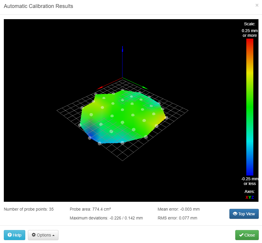
    Yes no difference with M401 or M402. It seems to ignore everything in bed.g so I am not sure what is actually running when initiating the mesh calibration. It does not first G28 home or m190 heat the bed. It just goes straight down towards the bed when I hit go. Obviously no probe deploying either.

    1 Reply Last reply Reply Quote 0
    • undefined
      Phaedrux Moderator
      last edited by 5 Aug 2018, 02:34

      I don't think mesh compensation will do anything other that its own probe routine. Any homing and delta calibration should be done first I believe.

      Z-Bot CoreXY Build | Thingiverse Profile

      1 Reply Last reply Reply Quote 0
      • undefined
        infamous_panda
        last edited by 5 Aug 2018, 13:44

        Jeez, rookie mistake. I misread the interface and did not realize that auto bed compensation was a button. I had thought that it was only a drop down menu and those were the options I had.

        Thank you so much. I'm now one step further.

        0_1533476634242_Capture.PNG

        1 Reply Last reply Reply Quote 0
        • undefined
          eMadman @dc42
          last edited by eMadman 18 Sept 2018, 02:40

          @dc42 said in Duet 2 Maestro BLTouch Wiring:

          You should be able to connect the BLTouch entirely to the Z probe connector. The 5th pin on the Z-probe connector provides +5V, and you can use the MOD pin on the Z probe connector as the servo pin.

          The BLTouch seems to have two GND pins - one for the z-probe, another for the servo.
          0_1537238312496_3c68f7e5-38be-4e94-81a3-379f38def905-image.png

          0_1537238222215_f9535b42-da88-4ca4-9887-db7802dcf74c-image.png

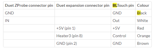
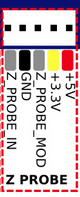
          Can I use the +3.3v pin on on the z-probe connector as the second GND?

          undefined 1 Reply Last reply 22 Sept 2018, 18:23 Reply Quote 0
          • undefined
            dc42 administrators
            last edited by 18 Sept 2018, 06:41

            No, but you can connect both ground pins of the bltouch to the ground pin on the Z probe connector.

            Duet WiFi hardware designer and firmware engineer
            Please do not ask me for Duet support via PM or email, use the forum
            http://www.escher3d.com, https://miscsolutions.wordpress.com

            1 Reply Last reply Reply Quote 1
            • undefined
              eMadman
              last edited by 18 Sept 2018, 13:42

              Awesome, thanks! I think this would be valuable information for the wiki - there's not enough there on how to set up the bltouch with the Maestro. I'm still new to the Duet boards and quite a ways off from getting mine running else I'd add some content there

              1 Reply Last reply Reply Quote 0
              • undefined
                cabal2000 @eMadman
                last edited by cabal2000 22 Sept 2018, 18:23

                @emadman @dc42
                SO let me get this right
                Black/brown - ground
                Red - 5Volt
                White - Z_PROBE_MOD
                Orange - Z_PROBE_IN

                undefined 1 Reply Last reply 22 Sept 2018, 21:36 Reply Quote 0
                • undefined
                  genghisnico13 @cabal2000
                  last edited by 22 Sept 2018, 21:36

                  @cabal2000 Almost, I installed mine yesterday:
                  Black/brown - ground
                  Red - 5Volt
                  Orange - Z_PROBE_MOD
                  White - Z_PROBE_IN

                  undefined 1 Reply Last reply 23 Sept 2018, 01:18 Reply Quote 0
                  • undefined
                    cabal2000 @genghisnico13
                    last edited by 23 Sept 2018, 01:18

                    @genghisnico13 Thanks brother. Ordered a BLtouch yesterday. Been trying to configure a Orion Piezo for the past week in which I have given up on it, Plan B=BLTouch!!!

                    1 Reply Last reply Reply Quote 0
                    • undefined
                      dc42 administrators
                      last edited by 23 Sept 2018, 10:54

                      I have updated the instructions for connecting a BLTouch on the wiki.

                      Duet WiFi hardware designer and firmware engineer
                      Please do not ask me for Duet support via PM or email, use the forum
                      http://www.escher3d.com, https://miscsolutions.wordpress.com

                      undefined 2 Replies Last reply 29 Sept 2018, 23:25 Reply Quote 0
                      • undefined
                        cabal2000 @dc42
                        last edited by 29 Sept 2018, 23:25

                        @dc42
                        This is what I have in the config.g for ES and Z-Probe
                        ; Endstops
                        M574 X1 Y1 S0 ; Set active low endstops

                        ; Z-Probe
                        M574 Z1 S2 ; Set endstops controlled by probe
                        M307 H3 A-1 C-1 D-1 ; Disable heater on PWM channel for BLTouch
                        M558 P9 H5 F100 T2000 ; Set Z probe type to bltouch and the dive height + speeds
                        G31 X0 Y0 Z0 P25 ; Set Z probe trigger value, offset and trigger height
                        M557 X15:285 Y15:285 S20 ; Define mesh grid

                        Wiring
                        Red-5volt
                        Orange Z_Probe_MOD
                        Black and Brown- Ground
                        White - Z_PROBE_IN

                        Red light on the BL-Touch just keeps blinking and does nothing.

                        undefined 1 Reply Last reply 29 Sept 2018, 23:57 Reply Quote 0
                        • undefined
                          cabal2000 @cabal2000
                          last edited by 29 Sept 2018, 23:57

                          @cabal2000

                          NEVERMIND!!!1
                          Got that figured out but now I am getting a "Error: Invalid servo index 3 in M280 command" error when i try a test

                          1 Reply Last reply Reply Quote 0
                          • undefined
                            cabal2000 @dc42
                            last edited by 30 Sept 2018, 00:25

                            @dc42 Is there a PINOUT diagram for the Maestro? I am thinking my issue is I have the wrong pin set in the config files

                            1 Reply Last reply Reply Quote 0
                            • undefined
                              dc42 administrators
                              last edited by dc42 30 Sept 2018, 08:18

                              https://duet3d.dozuki.com/Wiki/Duet_2_Maestro_Wiring_Diagram

                              Use pin 64 (P64) in the M280 commands, and don't use I1. You don't need to use M307 to disable a heater.

                              Duet WiFi hardware designer and firmware engineer
                              Please do not ask me for Duet support via PM or email, use the forum
                              http://www.escher3d.com, https://miscsolutions.wordpress.com

                              undefined 1 Reply Last reply 30 Sept 2018, 22:44 Reply Quote 0
                              • undefined
                                cabal2000 @dc42
                                last edited by 30 Sept 2018, 22:44

                                @dc42
                                Thanks DC42. That did the trick. Was getting tired when I was reading up on it all. Very VERY new to duet boards, was using Ramps before this and had that pretty much figured out when I switched over. Maybe its time to start a Maestro only Wiki??

                                1 Reply Last reply Reply Quote 0
                                • undefined
                                  dc42 administrators
                                  last edited by 1 Oct 2018, 06:50

                                  A separate Maestro-only wiki would involve a lot of duplication because so many things are the same as for the other Duets. I updated the section on connecting and configuring a BLTouch to cover the Maestro immediately after I posted my previous reply.

                                  Duet WiFi hardware designer and firmware engineer
                                  Please do not ask me for Duet support via PM or email, use the forum
                                  http://www.escher3d.com, https://miscsolutions.wordpress.com

                                  undefined 1 Reply Last reply 11 Nov 2018, 21:21 Reply Quote 0
                                  • undefined
                                    gnydick @dc42
                                    last edited by 11 Nov 2018, 21:21

                                    @dc42 I can't figure out where the heck the GPIO pins are in the wiring diagram for the maestro. Help!

                                    T3P3Tonyundefined 1 Reply Last reply 12 Nov 2018, 09:23 Reply Quote 0
                                    • T3P3Tonyundefined
                                      T3P3Tony administrators @gnydick
                                      last edited by 12 Nov 2018, 09:23

                                      @gnydick GPIO for what?There is a small Expansion header:
                                      0_1542014590087_7cd888e6-cfed-437f-97d0-48b34397d2de-image.png

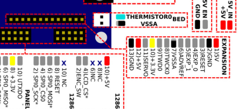
                                      But the Maestro has less expand ability than the other Duet 2s.

                                      www.duet3d.com

                                      undefined 1 Reply Last reply 12 Nov 2018, 11:52 Reply Quote 0
                                      • undefined
                                        gnydick @T3P3Tony
                                        last edited by 12 Nov 2018, 11:52

                                        @t3p3tony I want to hook up LED lights, and I just need a signal pin and ground. I found all of the charts on the wiki, but mapping them to what's in the diagram isn't straight forward. I thought I had figured it all out, but after hooking everything up, nothing happened.I used TWD0/PA3 as logical pin 62. That was after pulling up two web pages side by side to map the wiring diagram to the "using servo, etc." page, to then map to the pinout page. There really should be a mapping of logical pin numbers to exact physical pin on the board.

                                        1 Reply Last reply Reply Quote 0
                                        • undefined
                                          dc42 administrators
                                          last edited by 12 Nov 2018, 12:58

                                          I have added expansion pin names to the table at https://duet3d.dozuki.com/Wiki/Using_servos_and_controlling_unused_IO_pins?#Section_Duet_2_Maestro. It should be able to use the TWD0 pin as GPIO provided that you never issue a M260 or M261 command. Sending either of those commands will configure the pin for I2C, making it unavailable as GPIO.

                                          Duet WiFi hardware designer and firmware engineer
                                          Please do not ask me for Duet support via PM or email, use the forum
                                          http://www.escher3d.com, https://miscsolutions.wordpress.com

                                          undefined 1 Reply Last reply 12 Nov 2018, 13:20 Reply Quote 1
                                          • First post
                                            Last post
                                          Unless otherwise noted, all forum content is licensed under CC-BY-SA