S-Curve/ sinusoidal , Jerk +acceleration
-
i can see the chart on my tablet, but not on my PC, something seems to block the url/domain on my PC. Thanks.
Some well working theory/basics:
Given a spring mass system with mass m and spring stiffness c and force excitation it follows:-
If the acceleration (force) is changed stepwise by amount k1, the amplitude a1 of the oscillation caused by this step is directly proportional to the step size k1.
-
If the acceleration is changed like a ramp with ramp rate k2, the amplitude a2 of the oscillation caused by the ramp start is directly proportional to the ramp rate k2.
It follows that a2 / a1 == k2 * sqrt(m / c) * k1. [EDIT: typo correction -> m/c corrected to sqrt(m/c)]
So depending on the ramp rate (or step size) and also on m/c, the generated oscillation has a bigger or smaller amplitude for a step wise change or a ramp - it depends on the system (m & c) and tuning settings (k1 & k2).
I didn´t include damping because with damping the results are by far not as obvious and beautiful - but in principle it is exactly the same. A real fdm printer is also a combination of mass/spring/damper systems, but one frequency will dominate (ringing) and the above is also still valid.The frequency (sqrt(stiffness/mass)) is naturally the same for ramp and step.
So in case one big wave is generated (ramp start) compared to a lot of smaller waves (s-curve), it must be bad timing if the ringing is worse with s-curve OR it might come from a2 / a1 = k2 * sqrt(m / c) * k1.
E.g. if one big wave is generated at acceleration start and the next bump/wave start follows at acceleration end with an unlucky phase shift, it will superposition and amplify (triangular s-curve). It is easy to add one big wave to another big wave, so that they amplify each other. But it is much harder to superposition many smaller amplitude varying waves (real s-curve) in a way that they amplify each other - which doesn´t mean it is not possible in principle.In the end the triangular acceleration profile might be an unlucky profile to compare s-curve with the step wise acceleration change !
So depending on the above the ringing test results may vary. In general, many fdm printers will have comparable m/c and k2/k1 (k1 and k2 can be set anyhow). I didn´t check if this can be a game changer for some fdm printers. But there are very stiff and light (m/c is very small) as well as heavy and soft printers (m/c very high) out there....
-
-
@vp said in S-Curve/ sinusoidal , Jerk +acceleration:
Given a spring mass system with mass m and spring stiffness c and force excitation it follows:
-
If the acceleration (force) is changed stepwise by amount k1, the amplitude a1 of the oscillation caused by this step is directly proportional to the step size k1.
-
If the acceleration is changed like a ramp with ramp rate k2, the amplitude a2 of the oscillation caused by the ramp start is directly proportional to the ramp rate k2.
It follows that a2 / a1 == k2 * m / c * k1.
Only if the proportionality constant is the same in both cases. Is it?
The frequency (sqrt(stiffness/mass)) is naturally the same for ramp and step.
So in case one big wave is generated (ramp start) compared to a lot of smaller waves (s-curve), it must be bad timing if the ringing is worse with s-curve OR it might come from a2 / a1 = k2 * m / c * k1.
Yes, it is bad timing. With stepwise acceleration, the first frequency at which the oscillations produced by the start and end of the step cancel each other out is when 1/T where T is the length of the step. With triangular profile S-curve acceleration, it is 2/T where T is the total length of the triangular pulse.
In the end the triangular acceleration profile might be an unlucky profile to compare s-curve with the step wise acceleration change !
I am fairly sure that a trapezoidal acceleration profile will give results between the step case and the triangle case (because at the extremes it becomes one or the other), but I haven't done the maths yet.
-
-
Some input from my side - i am also surprised, but a triangular speed change doesn't seem to improve ringing at all times compared to a rectangular one. I would be glad if somebody finds a mistake below
1. What happens in between a speed change ?
For a mass spring system like m * xdotdot +c * x = c * y(t) with y(t) as a step or ramp follows:the position over time equals for a step wise change of y(t)
x(t) = (k_step * t^2)/2 - (k_step * m)/c + (k_step * m * cos((c^(1/2) * t)/m^(1/2)))/c
and for a ramp wise change of y(t)
x(t) = (k_ramp * t^3)/6 + (k_ramp * m^(3/2) * sin((c^(1/2) * t)/m^(1/2)))/c^(3/2) - (k_ramp * m * t)/c
k_step is the step size/acceleration [m/s^2] and k_ramp the ramp rate [m/s^3].
So every change of the acceleration causes a wave. Many acceleration changes causes many waves and these waves get superpositioned, that means they are just summed up. A rectangular acceleration profile consists of 2 stepwise changes of the acceleration - it produces 2 waves, which interfere. A triangular one creates 3 waves, because 3 ramp wise changes are needed.
The amplitude of the possible oscillations (ringing) is defined by k_step * m/c in the step case and k_ramp * sqrt(m)^(3/2)/c^(3/2). This is just the amplitude of a single wave, not the superposition of many waves.
Which method (ramp or step) does produces bigger waves ?
Dividing k_ramp * sqrt(m)^(3/2)/c^(3/2) by k_step * m/c leads to k_ramp/k_step * sqrt(m/c). By that the ratio of the amplitudes is a function of c/m.The frequency doesn´t change, it is defined by the system itself - not by the applied motion profile.
If the speed has to be the same after the same time for a rectangular shaped acceleration change as for an triangular shaped one of a certain pulse width, k_ramp equals to 4 * k_step/pulse_width. Substituting this k_ramp into k_ramp/k_step * sqrt(m/c) gives amplitude_ramp/amplitude_step = 4 * sqrt(m/c) / pulse_width.
So depending on sqrt(m/c) and the pulse width, the oscillations during the speed change can be higher or smaller, comparing a rectangular or triangular shaped acceleration change profile. BTW sqrt(c/m)/2/pi is the natural frequency and 2 * pi * sqrt(m/c) the period time T.
In other words, if the pulse width is bigger than 2 * T/pi a single ramp produces smaller waves than a single step, used in a rectangular or triangular profile.The natural frequencies f of the most important parts (steppers, belts, tubes) of my stiff/fast 3d printer are in the range of 300 - 70 Hz, or periods of 0.003 to 0.015 s. They can oscillate alone at their own natural frequency or all together with frequencies close to the smallest frequency. My slow printer is about factor 10-50 "slower" and less stiff. If damping is increased, these frequencies get smaller.
I use printing accelerations > 1g on my fast printer, so if the acceleration takes 0.01 s (pulse width) with 1g, the speed increases by > 100 mm/s.
In this case amplitude_ramp/amplitude_step = 2 * T/pi/pulse_width --> 2 * 0.003/pi/0.01 = 0.19 and 2 * 0.015/pi/0.01 = 0.96. So the fast parts gets 0.19 times less excited by the ramp, the slow parts not really.If the speed change would be only 25 mm/s, it would only take 0.0025 s and by that a triangular acceleration profile would generate bigger waves compared to a rectangular one. Because in the middle of the triangular shape we need a "double" sized ramp rate change to flip the sign of the acceleration change, the triangular shaped change can be even worse .
On my slow printer c/m is much smaller, but also the used acceleration, so in total it also ends up, that triangular can be better but doesn´t have to. To make it even more complex, depending on the various parts (steppers, belts, tubes etc.) and their different natural frequencies, it can be that the steppers would need a triangular shaped acceleration change and the belts a rectangular....
In case the pulse width equals to the period time T, "amplitude triangular / amplitude rectangular = 2/pi". That means the produced single waves comparing a single step with a single ramp, will be by a factor of 0.64 smaller in the ramp case
2. What does a fourier spectrum of a triangular pulse and rectangular pulse show ?
It just shows the amplitudes after applying the total speed change. It doesn´t show what happens during the speed change. Above equations show it.
The Fourier transform of the rectangular and triangular change show which frequencies gets excited by the rectangular and triangle acceleration profile. If the fourier shows the amplitude is zero for e.g. all frequencies with multiples of period T, these frequencies doesn't get excited by the speed change as a whole. If this is the natural frequency of the mass spring damper system sqrt(c/m)/2/pi, it means the total oscillation of the total speed change will be zero. It doesn't mean, that there are no oscillations happening during the speed change. Only the superposition of all waves together is zero.Because we talk about ringing, for pure x/y/z printers we don't see ringing during the speed change in our prints, we see it after the speed change has been done. But for all others (deltas scaras, Hs, etc.) the ringing during the speed change will also create artifacts.
Damping (which is significant) is also not included. Therefore the zero amplitude positions are just not there - at least by far not perfectly.
The fourier spectrum also doesn't compare the maximum total deviation of the target and actual trajectory, it just compares the amplitudes. This is ok, as long as we only compare ringing. To compare dimensional accuracy, this would be wrong.
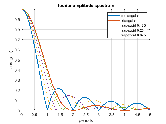
The fourier spectrum shows:
- The rectangular acceleration change has cancellation positions at multiples of T.
- The triangular acceleration change has cancellation positions at multiples of 2 * T.
- Above 1.29 * T the triangular shape is - excluding all of the above written - better as the rectangular shape and vice versa.
- A triangular shape can be blended into a rectangular one, using a trapezoidal shape (but that doesn't mean that all, that all possible shapes are included in this comparison).
- Close to zero (< 0.2 T), there is not significant difference between different profiles - that is our normal operating position.
- The rectangular change excites higher frequencies much more than the triangular one, this is because of the sharp edges of the step.
- Using different trapezoid shapes, it is possible to generate cancellation locations “everywhere” between the rectangular and triangular profile.
The following Fourier spectrum compares different acceleration profiles, which all have the same pulse width and same end speed.
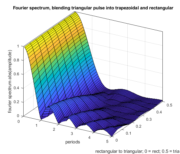
Another figure to show how a rectangular change can be blended into a triangular one using a trapezoidal shape.
-
3. How to utilize the cancellation points ?
From the Fourier transform we know, we could have no ringing after (that doesn't mean not in between) a speed change. To be able to use the zero amplitude positions to cancel the total ringing of a complete speed change, we have to know the period time which is 2 * pi/sqrt(c/m). Unfortunately c/m is by far not constant and not only one c/m has to dominate. It will vary among different fdm printers by a factor of up to 100 and it will vary also during a print. E.g. on a prusa style printer with a moving bed, the mass as well as the stiffness changes significantly. For the 1st layer c/m is big and for the last layer e.g. 200 mm above the bed with 500 g printed c/m will be very small, depending on the shape of the print, it might vary arbitrarily. On ultimaker style printer the same is valid, in a corner the stiffness is max and in the middle min. If the stepper current is doubled, c/m of the stepper is doubled. If the current of the stepper drops at high velocities, c/m of the stepper follows.... so c/m is not constant and in addition there is more than 1 mass spring damper system acting !So in total the length of a speed change would have to be adjusted during the print - to hunt the cancelation points. I don´t claim that this couldn´t be done (in theory), but for e.g prusa printers it won´t be doable or only in certain cases. On ultimaker style printers it will "only" work near e.g. the middle of the bed and as long the stepper current doesnt drop to much due to speed.
In my case my stiff printer has (stepper, belts and tubes) c/m values in the range of 1e5 to 1e6 [N * kg/m]. My slow printer has c/m values about 1e3 to 1e4 [N * kg/m].
A c/m of 1e6 gives a period time T of 2 * pi/sqrt(1e6) = 63ms (or 160 Hz); a c/m of 1e3 gives 199 ms or 5 Hz.
My stiff printer uses printing accelerations > 1g, so in 63 ms the speed change after one period time T of acceleration is > 10.000 * 0.063 = 630 mm/s. With 0.2 g at my slow printer the speed change would be 2000 * 0.2 = 400 mm/s. In other words the nowadays used acceleration settings just "mirrow" c/m and the time used for acceleration when printing is between 0 and << 0.1 - 0.2 * T. The fourier transform doesn´t show a significant difference there between different moveplan profiles - but the amplitudes of the waves generated during the move differ.So if we would print using speeds like before, we would have to reduce the acceleration to catch the 1st wave cancelation point at 1 * T. Increasing the acceleration time will amplify extrusion problems. In addition i don´t want to print slower....
If we would hunt for the 1st wave cancelation point by increasing the max speed, we would get really high speeds, with the need for "max. acceleration as a function of speed" and a working pressure advance.
In case we ask for multiple speed changes (moveplan) and not for a single speed change, the cancelation possibility gets more interesting. Multiple speed changes in a row can stimulate much lower frequencies as a single speed change. So we know that normally a single speed change operates at e.g. << 0.2 T. But multiple speed changes together could easily stimulate at or above 1 T. The high level move planner would have to adjust the move plan in a way, that the speed changes itself act close to the cancelation points. This could be beneficial for a lot of small moves in a row. E.g. when printing top and bottom layers and it fills a gap by zigzag moves.
4. Is a triangular profile a good choice to compare s-curve acceleration with a rectangular change ?
In addition to above, yes and no. It is true that one can blend the fourier transform from a triangle over a trapezoid into a rectangle (see the figure below). But whos says that we have to limit it to that simple kind of shapes ?Just try the following: instead of one triangular shape apply 2 after each other. Both have the half width of the single one and same amplitude. By that the frequency spectrum is shifted to the left by T/2 and the 1st wave cancelation is also at 1 * T, like in the rectangular case (and not like 2 * T in the single triangular case). So comparing a triangular with a rectangular profile just compares two profiles and not all available possibilities.
5. The main fdm problem is extrusion - not ringing.
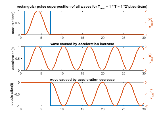
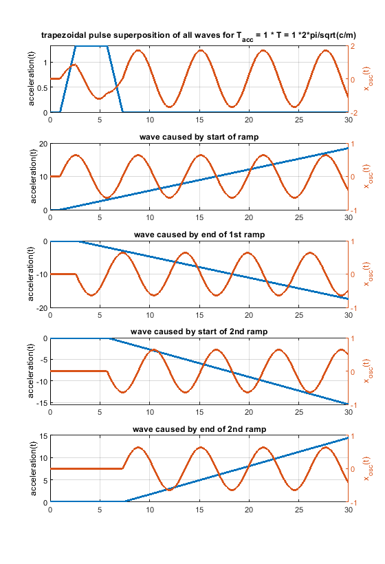
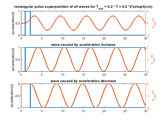
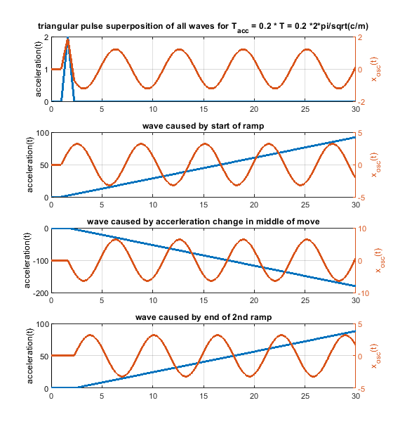
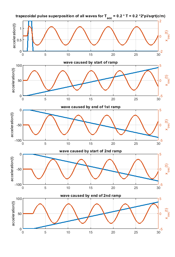
Ringing can be solved by proper engineering. Extrusion is thermodynamically and fluid wise limited - these limits "cannot" be changed - at least not much. Pressure advance would help a lot, if it would have a chance to work. With a stepwise acceleration change, it can only work under certain limiting conditions. With “s-curve” (a more gentle) acceleration the pressure advance jerk problem caused by the step wise acceleration change would be "wiped away". Pressure advance could show its potential.6. Because one picture says more than 1000 words, i have attached some figs for a system like m * xdotdot +c * x = c * y(t) (so no damping and only one spring mass system). m = c = 1.
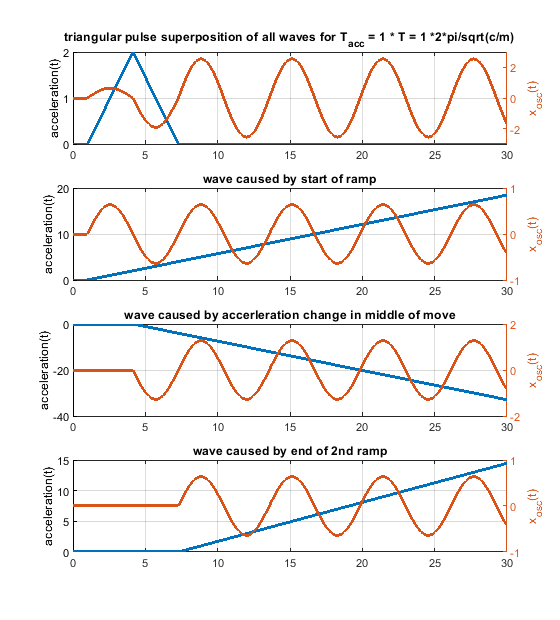
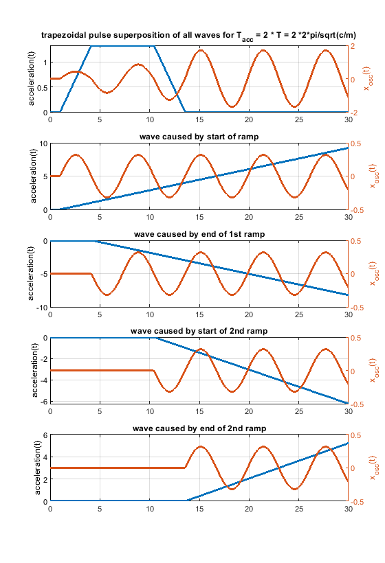
In case the acceleration time equals to the time period T, as shown in the fourier transform, the whole rectangular acceleration change produces no remaining waves (only without damping, with damping like in real life this doesn´t work perfectly at all). The triangular as well as trapezoidal acceleration change show waves - which would be damped quickly including damping, but this is the ringing we see on pure x/y/z printers.
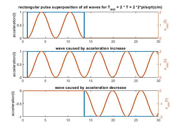
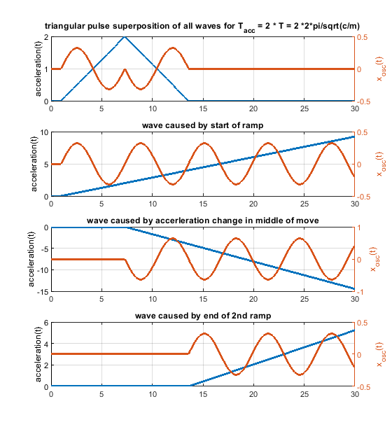
Blue is the acceleration change ydotdot(t), orange is only the oscillation part of x(t).
Same for acceleration time equals to the time period T * 2 - now the triangluar change also produces no remaining waves. If instead of one triangle of width "a" 2 triangles of width "a/2" and the same height would be applied, the triangular profiless also would also show no remaining waves at 1 * T - like the rectangular case.
The same for a pulse width of 0.2 T. In real life it looks much better, because damping acts.
-
Just my 2 pence worth, reading this thread it is going to be of great benefit to some but make no difference to others.
From a practical perceptive it would be most useful to have S-curve available under an M-code, it could then be used per print.
I've used it on my Cartesian before I got my Duet (using Marlin2 and an MKS-Sbase) it does allow me to print faster at the same quality, Plus my desk didn't vibrate as much
")
However it did have those awful stepper drivers, so theres that.
-
@stewwy the option to select which acceleration type is used is part of the plan.
-
When S-curve acceleration is applied will the curve look more like this picture instead of a trapezoid? I got the picture off of the prusa calculator website.

-
That picture doesn't illustrate S-curve acceleration.
-
Is this what is trying to be achieved?
If so, do we also need to think about the timing ? As it effectively moves the area under graph in a positive way which is going to lead to an overrun. or am I over-thinking this?
Apologies if this has already been discussed, I didn't notice it on a quick re-read of the thread.
-
The problem with changing the profile like that is that it makes the total acceleration and deceleration times longer, which slows the print down. You could keep the trapezoidal profile but reduce acceleration and deceleration to lengthen the acceleration and deceleration phases instead, and that too would typically reduce ringing.
To get an accurate comparison, you need to use a higher peak acceleration in the S-curve profile than you do in the trapezoidal profile, so that the total acceleration time is the the same in both cases. Similarly for deceleration.
Duet WiFi hardware designer and firmware engineer
Please do not ask me for Duet support via PM or email, use the forum
http://www.escher3d.com, https://miscsolutions.wordpress.com -
Did you say higher pint speeds?
-
@dc42 makes sense, heading towards the classic bell shaped curve, if you had unlimited speed and limited acceleration that is where you would want to be anyway.
-
just for info: I saw the TMC5161 uses S-Shaped motion. I'll test whether it reduces vibrations at the extruder.
-
I am using printer with ball screws and I can say that for me S-curve is really important. While belt motion got some elasticity ball screw got 0. This is really cool as I have no ringing at all and really smooth print but I need to live with very low Jerk and acceleration settings like 200 Jerk and 300 acceleration. If I got faster the ball screws start producing noise like hammering during direction change. Current jerk implementation is just stupid. It is okay to change the speed with jerk but it is not okay to change the direction with half of the jerk speed. So I am really waiting for S-curve to come as it really will make my system to perform really well and to be silent.
-
@neonode What size of ball screws are you using (length, diameter and pitch) and what size of stepper (NEMA* and the torque)?
-
@dc42 said in S-Curve/ sinusoidal , Jerk +acceleration:
Unfortunately, in 3D printing we have a much worse problem, which is that curves are approximated by straight lines. This unfortunately forces us into making the first derivative of position discontinuous, to avoid dropping the speed to zero at every boundary between line segments in a curve. As long as we are forced to do this, there is very little point in worrying about the discontinuity of the second derivative.
If we ever reach the situation where the model files we slice represent curves properly, and the slicers that generate gcode from them generate Bezier curves, cubic splines or some other representation of curves, then implementing smooth changes in acceleration may be worth looking into.
Yes, but that would also mean whole new generation of modelling tools, gcode, slicers - generally the whole toolset. Can't we have a feature which approximates segmented movement using curves? Supporting curves way down the pipeline in the firmware is a thing that can be reused once the slicers are up to par.
The thing about curves is that nothing is a 100% curve. The 3d models are meshes or a mix of corners and curves that would otherwise need to be approximated somewhere, be it in firmware (if hardware permits) or PC application software as a pre-processing step.
-
@neonode I agree!! The line segment jumps can be handled with filtering in the servo driver even if that is not a perfect solution.
-
I agree with trying out s-curve. My printer is turning out great, and I want higher speed printing.

These ripples are more visible than they are palpable, but the corner ringing is detectable to the touch.
https://dyzedesign.com/2016/10/printing-300-mm-s-part-1-basics-hardware/
https://www.controleng.ca/servosoft/SSHelp1033/source/MotionProfile.htm
I'm making another post with the photo with a different topic, keep an eye out
")
-
Have you looked at the dynamic acceleration control feature in RRF 2.02RC6? It may help you to control the ringing. See https://duet3d.dozuki.com/Wiki/Gcode?revisionid=HEAD#Section_M593_Configure_Dynamic_Acceleration_Adjustment.
Duet WiFi hardware designer and firmware engineer
Please do not ask me for Duet support via PM or email, use the forum
http://www.escher3d.com, https://miscsolutions.wordpress.com -
@dc42 worth a try. Still would like s-curve. I'm not too worried about being slightly slower, my printer is printing cleanly at 150mm/sec, probably could go faster if I had a more powerful system of drivers and motors.