Dotstar questions?
-
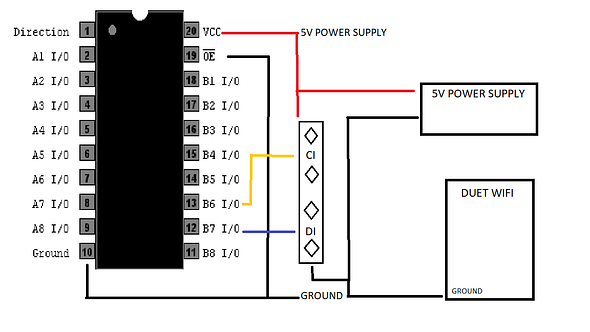
I just have a few questions regarding using a strip of Dotstar led's on my WiFi board.I have a few CD74HCT245E and just wanted to ask if they can be used for this application and if I have the wiring right?I also would like some help on the wiring on the Duet side along with how to control them?
-
Hi Siblues
The chip CD74HCT245E will work for 3.3V to 5V conversion
At this point in time, I would recommend you use a Teensy LC to control the DotStars instead of connecting to the Duet. Reason being...
- if you are new to electronics, it'll be easier to start with Arduino code that controls DotStars
- the M150 command documented https://duet3d.dozuki.com/Wiki/Gcode#Section_M150_Set_LED_colours does not seem to be actually ready for use in RepRapFirmware, rebuilding RepRapFirmware is not a trivial task
- since M150 is not implemented, I can't tell you which pins to use
- if you wish the DotStars to show you anything fancy, like indicate temperature or print progress, then again, that would require you to rebuild RepRapFirmware
So I suggest you get a Teensy, or Arduino Micro/Nano, and use it to control the DotStars. Personally I have a small project using a ATtiny2313 (think of it as a 2KB Arduino, very small and cheap) that will monitor the temperature of my printer by intercepting the communication between the Duet and PanelDue, it would be easy for me to make the ATtiny2313 to control a strip of DotStars to indicate temperature this way (that's not what my project is, but I am saying I could do it this way if I had to)
If you really want a gcode macro to control the DotStars, perhaps you can program your Teensy/Arduino to become a I2C slave device, and use the M260 gcode https://duet3d.dozuki.com/Wiki/Gcode#Section_M260_i2c_Send_and_or_request_Data to command it.
In almost all cases, if you want any fancy animation, I highly recommend NOT coding the animations into the Duet firmware, instead, run animations from a Teensy/Arduino instead. Otherwise, either you have to rebuild RepRapFirmware yourself (and frequently), or have a crap ton of M150 commands somewhere (which cannot run parallel with a print).
edit: I also foresee difficulty in implementing DotStar code into RepRapFirmware. You can't just connect the DotStars to the SPI port because other things use that port, talking to a temperature sensor would make the DotStars go nuts. That means plain GPIOs, but then you can't implement bit-bang SPI without considering possible timing problems, which are kind of important for a 3D printer. So... at best, maybe auxiliary fan speed controls can be hijacked for PWMing ordinary dumb LEDs, but not DotStars. A Teensy/Arduino could also read in a PWM signal and convert it into control signals for DotStars.
-
I would not even know where to start as far as coding goes. I just needed some lighting in order to check the prints while they are in progress and maybe for the camera lighting. I also wouldn't have minded maybe a color change to indicate print completion but it's no big deal maybe I will just use a simple on off set of single color LEDs for lighting.
-
Since you got the DotStars already, it's a good thing to learn. They cost much more than plain RGB LED strips so I figured you got them for some fancy animations that required individual LED control. Go get an Arduino and practice a bit, there are plenty of example code for DotStars, including fancy animations. Check Adafruit's website, they'll have plenty of tutorials.
For one idea, try programming your Arduino to be a I2C slave. When Duet starts or finishes a print, you can run a macro with the M260 code, then when the Arduino receives the I2C data, it can go into whatever color you want, white for printing, and maybe green for finished.
Although if you are trying to save money, the better idea is probably just to use extra fan PWM signals for an ordinary dumb RGB LED strip. Save the DotStar strip for something that needs it (I made this last year https://eleccelerator.com/car-heads-up-display-using-led-strip/ )
-
I love that HUD you made that was a very cool idea.I will have the Dotstars handy for my next project.I must have almost 40 feet of leds here for my multirotors and other projects and I have tons of Teensy's and Nano's laying around so I am sure I will use them eventually.I guess I will pick up a set of 5v dumb led's for the simple on off set up I need.
-
We have some code for driving DotStar LEDs. It's in the src/Fans subfolder of the RRF source. However, it's written to use a USART directly. For the Duet WiFi, it would be better to use the SharedSPI subsystem.
In terms of hardware, the DotStar doesn't have a CS input. Therefore if you are sharing the SPI signals with other devices, you need to gate the clock signal. I would use a 74HCT02 as a driver for the DotStar. Use two of the gates in the package connected in series to level-shift the MOSI signal to 5V. Use the 3rd gate to invert the SCL signal, then use the 4th gate to gate the output of the 3rd gate with your chosen CS signal.
I'd be happy to enable that code on in the standard build of RRF for the Duet WiFi, connected as described above.
Caution: DotStar LEDs can take a lot of current, up to around 80mA per LED if you turn all of RGBW on. So you shouldn't use the 5V power output of the Duet to power more than about 15 of them.
Duet WiFi hardware designer and firmware engineer
Please do not ask me for Duet support via PM or email, use the forum
http://www.escher3d.com, https://miscsolutions.wordpress.com -
I am still trying to grasp learning how to use the Duet which is a steep learning curve for me.The gates you are referring to and wiring them up correctly without frying something are probably a bit beyond my know how at the moment.I will probably stick to a strip of 5v white leds for simple on/off control in order to light the bed.
-
David,
Was this code ever implemented ?
I presume connection is via the Therm Board connector ?
I have a circuit diagram fleshed out based on your notes above ..... with CS jumpered to either CS1 through 4.
The obvious caveat is that the thermocouple usage wold be limited to 2 max ?
Also, what would the M150 command look like ? Eg .... for using CS3
( I have working discrete 24v LED driver strips working on other machines via the fan outputs .... I just fancy having a go at this.... maybe make a PCB if enough people are interested .... )
Thanks
Keith -
@TKWARD said in Dotstar questions?:
Was this code ever implemented ?
Yes, in the standard firmware build for Duet 3. Not in the Duet 2 build. It could be added to the Duet 2 build but you would need some external gating and level shifting hardware to interface with the DotStar strip.
Duet WiFi hardware designer and firmware engineer
Please do not ask me for Duet support via PM or email, use the forum
http://www.escher3d.com, https://miscsolutions.wordpress.com -
That's what I was alluding to. I can design a cheap pcb with the 74HCT02 and some connectors ( with a set of jumper to select an appropriate CS ).
Would the firmware changes be added just for this project ? Or, does it need to be added to the features 'wishlist' for Duet 2 firmware ?
I'll post a circuit diagram in the coming days for the potential design.
-
-
See replies below ...miss-tagged them ... there is a pdf with potential circuit diagram of addon board
-
I wouldn't use as much as 1000uF between Vcc and ground (100uF should be enough), but otherwise that should be OK. However, if you will be using a separate 5V supply to power the DotStar then you should take precautions against the Duet being powered but not the DotStar, or vice versa. A resistor of about 3K3 in series with each of Duet CS, SCLK and MOSI and the corresponding 74HCT02 connection should be sufficient.
Also the Duet and DotStar PSUs need a common ground, so it's probably best to link the grounds on that board.
-
@dc42 Thanks David.
The ground is definitely commoned.
I'll add the resistors as per your suggestion.
Would the firmware changes be added just for this project ? Or, does it need to be added to the features 'wishlist' for Duet 2 firmware ?
How would this be operated in terms of G code ? with M150 command ?
Also, assume that if a thermocouple board is used, only 2 of the CS would be available anyway ?
Thanks,
Keith
-
@TKWARD said in Dotstar questions?:
@dc42 Thanks David.
Would the firmware changes be added just for this project ? Or, does it need to be added to the features 'wishlist' for Duet 2 firmware ?
if you do ahead with this then I will enable DotStar support in RRF3. It will need a new configuration command (probably a variant of M150) to specify which CS line to use.
How would this be operated in terms of G code ? with M150 command ?
Yes.
Also, assume that if a thermocouple board is used, only 2 of the CS would be available anyway ?
Yes. So you might want to omit the jumper block and just wire it to use CS1. If you stack it on top of a daughter board then it would use CS3 instead automatically, because CS3 feeding into the daughter board is routed to the corresponding pin for CS1 on the top connector.
-
I'm going ahead with it.
Jumpers removed.
CS is set to CS_1.
Tank Capacitor value changed, and resistors added as per your suggestion.Just waiting on an assembly price from Chinese supplier.
I'd like to send you a few boards to test with the firmware. ( Take this offline and get address etc via pm ?? )
Thanks
Keith -
Any updates on the project so far? I'd be interested in the schematics for the board
")
-
Is it possible to skip some LEDs in the settings?
Lets say LEDs 1-10 are set to different colors.
I want to change LED2 without changing LED1. -
@cando415 no, just send the same setting again for the LEDS who do not change.
-
can you store that info somewere? which LED should get what state?