Controlling a Cetus3D with Duet3D 0.8.5
-
@fotomas said in Controlling a Cetus3D with Duet3D 0.8.5:
Is there more to it than using M569, M574 and coordinates in homing files?
To reverse the direction of the Y axis you also need to adjust M569, M574, and in homey.g and homeall.g reverse the directions of the Y homing moves and any Y homing stop backoff moves. See https://duet3d.dozuki.com/Wiki/ConfiguringRepRapFirmwareCartesianPrinter#Section_Homing_X_and_Y and https://duet3d.dozuki.com/Wiki/ConfiguringRepRapFirmwareCartesianPrinter#Section_The_homeall_g_file.
-
After a night sleep and some distance to the whole thing I sorted it out. I had almost right, the one thing that threw me of was one line I had added in homeall.g G92 X-3 Y-5. It was just an adjustment since my Y-axis home outside the printable area. But it surley messed things up
")
dc42 Thank you for your quick reply, now I am on the right track again.
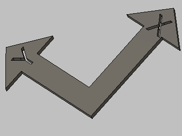
Oh, and this is the piece I drew to print verifying that the axis are in right order. It was after the print finished it dawned on me both letter X and Y can be mirrored, without showing. Bad luck when thinking, I guess
-
HI,
I'm considering doing the same, swapping out the default electronics with a Duet. I intend to use the sensorless homing feature, but I am not sure if that will work for the Z axis. For the Z-axis I still got three difference Z-axis sensors, the original three wire ormerod sensors, the 4 wire one, and the DC42 sensorboard with ultrasonic sensor. Am I right assuming you're using the latter as sensor? Or did you try sensorless home for that one as well?
And how may steps per mm did you configure for the extruder? -
@onno
I am using the earliest sensor made by dc42, dor an Ormerod with dual extruders. Link. I use it to home Z and Y axis, for the X axis I have mounted a micro switch besede the x-axis stepper motor.I will post the STL's for the sensor board, micro switch, power inlet and casing, if anyone is interested.
My config for the cetus looks like this, note the quite exotic heater values, but hey the work and have beed calibrated pretty well. I am using the cetus almost as delivered. 18v powerbrick, same extruder, same stepper motors. And tuned in it works very well, both with PLA and TPU, on original table without raft.
I am happy to answer any question you may have.
; General preferences G90 ; Send absolute coordinates... M83 ; ...but relative extruder moves ; Network M550 PCEDUT ; Set machine name Cetus + Duet => cedut ;) M551 Preprap ; Set password M552 P192.168.0.65 S1 ; Enable network and set IP address M553 P255.255.255.0 ; Set netmask M554 P192.168.0.1 ; Set gateway M586 P0 S1 ; Enable HTTP M586 P1 S0 ; Disable FTP M586 P2 S0 ; Disable Telnet ; Drives M569 P0 S1 ; Drive 0 goes forwards M569 P1 S1 ; Drive 1 goes backwards (Y) M569 P2 S1 ; Drive 2 goes forwards M569 P3 S1 ; Drive 3 goes forwards M92 X79.72 Y79.72 Z79.72 E118.00 ; Set steps per mm; used to be E127 M566 X230.00 Y230.00 Z90.00 E120.00 ; Set maximum instantaneous speed changes (mm/min) M203 X28000.00 Y28000.00 Z15000.00 E10000.00 ; Set maximum speeds (mm/min) M201 X200.00 Y200.00 Z100.00 E250.00 ; Set accelerations (mm/s^2) M906 X340.00 Y340.00 Z500.00 E500.00 I30 ; Set motor currents (mA) and motor idle factor in per cent M84 S30 ; Set idle timeout ; Axis Limits M208 X-10 Y0 Z0 S1 ; Set axis minima M208 X185 Y184 Z180 S0 ; Set axis maxima ; Endstops M574 X1 S0 ; Set active high endstops ; Z-Probe M574 Y2 Z1 S2 ; Set endstops controlled by probe M558 P1 H5 F250 T6000 ; Set Z probe type to unmodulated and the dive height + speeds G31 P538 X0 Y0 Z3.82 ; Set Z probe trigger value, offset and trigger height M557 X50:180 Y10:165 S40 ; Define mesh grid G29 S1 ; Load stored mesh grid from SD Card ; Heaters M140 H-1 ; Disable heated bed M305 P1 R4700 T112 B-425 C7.060000e-8 ; post multimeter measurement M143 H1 S280 ; Set temperature limit for heater 1 to 280C ; Fans M106 P0 T50 H1 ; Thermostatic control is on, turn on at 50cC ; Tools M563 P0 D0 H1 ; Define tool 0 G10 P0 X0 Y0 Z0 ; Set tool 0 axis offsets G10 P0 R0 S0 ; Set initial tool 0 active and standby temperatures to 0C ; Pressure advance M572 D0 S0.05 -
Thanks for the info, this provides a great starting point once I get the Duet in (still need to order it).
Right now the printer is still too busy to take it out, but like you, I'm trying to stay close to the original Cetus initially, although I foresee switching to an E3D Titan Aero at a later stage as well, along with 0.9deg steppers, and a heated bed.
Once again, thanks! -
@fotomas Thanks a lot for helpful infos. I’m getting Cetus MK3, which should arrive next month, and joined Cetus Duet club
How you connect Cetus powerbrick to Duet? Any modification needed?
Cookie
-
@cookie
I took a DC jack from an old DELL laptop docking station. 3D Printed a holder so I could screw it down to the Cetus bottom plate using an already existing hole.The Cetus bottom plate has four holes for the original controller board. Two of them fits the Duet 0.8.5 board as is. The 3D printed part for the DC jack reaches in underneath the the Duet offering support.

-
@fotomas great! Any photo of this dc jack? So I can google it and try to get one.
-
@cookie
I de-soldered one like in the pic below. But an Ebay or google search for "DC Jack female 7.4 mm" give you some other options.
-
Hi,
Another Cetus MK3 owner here. Just got my Duet Wifi, but of course don't want to start pulling cables and boards out of a working printer before I know I have everything and it's reasonably likely to work.
I think I'm going to need at least a different power supply (not a problem, I'll bring over a bench supply tomorrow). But is that probably it?
I'd also be super grateful if someone in the know, could post the high level overview of the process? I mean like what are the chapter titles; then I can go off and bang my head against figuring out the finer details of all that until it works..
Thanks

Dan -
dsmudger
I would say these are major steps
- Homing switches (I use a microswitch for X and an old dc42 IR sensor for Z and Y)
- Make adapters or get new cables to stepper motors
- Make adapter or new cable for hot end
- Power supply (I am using the original Cetus power supply)
- Configure the Duet3d (steps/mm and heater values you can see above, the rest I think may vary in your case)
Original connectors can be forced into the Duet board, but I ended up making adapters both for the steppers and the hot end. Pictures below show before the adapters during "proof of concept phase". On the hotend it self I made a new board using experimental circuit board and matching connectors. There was too much interference in the ribbon cable for the signal from the IR board so I added an ethernet (twisted pair) cable for that.
If there are any questions I would be happy to help.


-
Thanks a lot, that's beyond useful.
- Cetus MK3 already has 3x homing switches, so sounds like I might even already have all I need.
- Adapters seems the right way to go so it's easily reversible, but eh, 'ain't gonna need it
 '.
'. - Duet 2 Wifi came with a little bag of JST connectors; if I'm lucky, the metal crimp terminals might be the same. If so I'll just need to change the plastic shells over (while carefully counting on my fingers which colour goes to which pin). If I'm extra lucky and Cetus doesn't change their wiring too often, maybe it'll even match your photos and help confirm I'm on the right track

Big thanks again for that, I'll try to post something once I get things going

-
@dsmudger I just got my MK3 running and the Duet Wifi is laying around. Seem like I’ve to figure out the right crimping tools or learn how to crimp without them. I’m so novice when come to wiring works. Will keep you update when there is progress.
Thanks
-
re adapter: https://www.thingiverse.com/thing:3465278 is what i did for what may be the same "problem"
And JST XH terminals which Tiertime use aren't compatible with the molex picoblade, you will need to replace terminals, or as I did, buy male JST XH and make adapters just to make it reversible.
-
@fotomas said in Controlling a Cetus3D with Duet3D 0.8.5:
On the hotend it self I made a new board using experimental circuit board and matching connectors.
Hello, @fotomas
I'm working on MK3. The X,Y,Z motors and endstops are working as it should now. But when come to 16 pin connector wiring to hotend's motor, heater, thermistor and fan .. how you figured out which is which?
Thanks,
Cookie -
Dear @cookie
That is quite easy.
Just measure the connections between the Control board end and the daughter board that has separate connections for each "thing". Thermistor, stepper motor, fan, heater. If I remember correctly the hearer uses double wires for both + and -, most likely to increase the cable area.

-
They used the same layout on my Up Mini 2. Doubling the heater wires to increase current carrying capability of both wires and connectors. From your picture they use the same pinout as well.
-
@fotomas thanks!
I spend a few hours figured out, I’m a novice when come to electronic. I tried mapping out the circuit board and use thermistor to check each pair connectivity, then could identified them all
Then, Cetus use PT100 as thermistor. Did you swap out to something else or buy PT100 daugther board?
Also, you get new heater or not? And did you splice the wire for double heating pin, right? Still not sure how to do it right ..
-
I'm using the original cetus thermistor. It works well after finding the correct values for it.
I do not think a negative B value is common.
M305 P1 R4700 T112 B-425 C7.060000e-8 -
@fotomas said in Controlling a Cetus3D with Duet3D 0.8.5:
I'm using the original cetus thermistor. It works well after finding the correct values for it.
I do not think a negative B value is common.
M305 P1 R4700 T112 B-425 C7.060000e-8Looks like you are using a PT100 but you have connected it directly to the thermistor input. This will give you a very poor resolution and you should use the PT100 daughter board instead. However, if you want to use a direct connection then I suggest this:
M305 P1 X501 R47000
This says you are using a PT1000 sensor, but inflates the series resistor value by a factor of 10 to compensate for the fact that you are actually using a PT100.