Indirect (bearing) laser filament monitor concept
-
@dc42 I have a v2 monitor, and using the 2.03 firmware. Monitor is recognised as v2, until I send the A0 command from the console ; it is then recognised as v1. Sometimes it reverts to reporting v2.
-
@dc42 My foolish mistake - I was still running f/w 2.02
I have updated to 2.03-RC2 and can now see that my sensor is version 2 (and appears to be producing more reasonable values). -
@SteveYYC When did you buy your laser filament monitor? Does it have V2 on the board?
-
I think I'll be waiting for an updated design with a longer working distance to assemble and install mine. As for light leaks, how about some tape in a few spots? I have the adrianr52 version printed, and I find the slot is not wide enough for my bearings. My bearings are 3.98mm and my slots ended up 3.85mm or so.
-
@synapsis I bought it from spool3d.ca because they're local.
Yes, my board has v2.0 silkscreened on the side with the sensor.
-
There seems to be a linear relationship between the sensor distance and the average percentage reported:
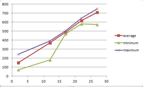
This is the percentage value returned is on the Y axis, and the distance between the sensor and bearing surface on the X axis. Looks as though it would give 100% with contact! Also looks as though the minimum returned is a bit more sensitive to distance than the maximum. -
@adrian52 That graph does an excellent job of showing the sweet spot of 17-22mm distance between the sensor and the bearing. I didn't expect it to be that sharply defined.
-
@3dmntbighker I did leave the centre of the bearing slot as a nominal 4mm, the region for the moving outer bearing being 4.2mm. So maybe its worth checking if the bearing/bolt is fully seated - on my print it takes a bit of a push for it to click in place, but then it rotates freely. Could post one with a bit more tolerance it that would help.
-
@steveyyc I tried making a double walled 15mm spacer, with an inner channel of 7x4mm, with a 3mm thick wall, linking the sensor to the bearing surface. I even put a little 0.5mm thick flap to block the LED shining into the sensor chamber. The results were very similar to those obtained with the plain 15mm spacer, so in my hands I don't think light leakage is a problem.
-
Sounds like an optimized design is in the near future. I could definitely use a bit more bearing clearance. I think the whole thing could be a bit wider with some bearing slop and room for a longer bolt. It seems like it's tighter in there than it needs to be to save a few mm outer dimension.
-
Great information!!!!!!
I used to compare the slicer predicted total length with the sensor reported total length. How does this correlate with the sensor distance?
-
@3dmntbighker I have put a new version on thingiverse, 3649565. I have increased the play, and made the bolts screw in from the side. This is easy for the bottom bearing, but you need a 7mm bolt for the upper bearing to fit between the vertical bolts. Their spacing is determined by the holes on the PCB.
I have done more experiments with the gap between sensor and top bearing, and have concluded so far that a 5mm spacer is probably ok. I realised that my initial results were essentially single points for the max and min - with repeated runs, the picture is not so clear, but I think 5mm is better than no spacer.
The percentages I get are still high, but quite reproducible - for the 5mm spacer, the average is about 270%, with the min not below 259, and the max not above 287 on 4 runs of at least 500mm extrusion. The relationship between sensor distance and average percentage reported is very linear - I have 12 points in my dataset now, with a least squares linear fit r squared of 0.998. The slope is 23.0 - the average percentage increases by 23 for each mm of gap between the sensor and bearing surface.
-
@adrian52 said in Indirect (bearing) laser filament monitor concept:
@3dmntbighker I have put a new version on thingiverse, 3649565. I have increased the play, and made the bolts screw in from the side. This is easy for the bottom bearing, but you need a 7mm bolt for the upper bearing to fit between the vertical bolts. Their spacing is determined by the holes on the PCB.
I have done more experiments with the gap between sensor and top bearing, and have concluded so far that a 5mm spacer is probably ok. I realised that my initial results were essentially single points for the max and min - with repeated runs, the picture is not so clear, but I think 5mm is better than no spacer.
The percentages I get are still high, but quite reproducible - for the 5mm spacer, the average is about 270%, with the min not below 259, and the max not above 287 on 4 runs of at least 500mm extrusion. The relationship between sensor distance and average percentage reported is very linear - I have 12 points in my dataset now, with a least squares linear fit r squared of 0.998. The slope is 23.0 - the average percentage increases by 23 for each mm of gap between the sensor and bearing surface.
You are a rock star
")
-
Great job, have duet laser sensor on order and can't wait to try this.
-
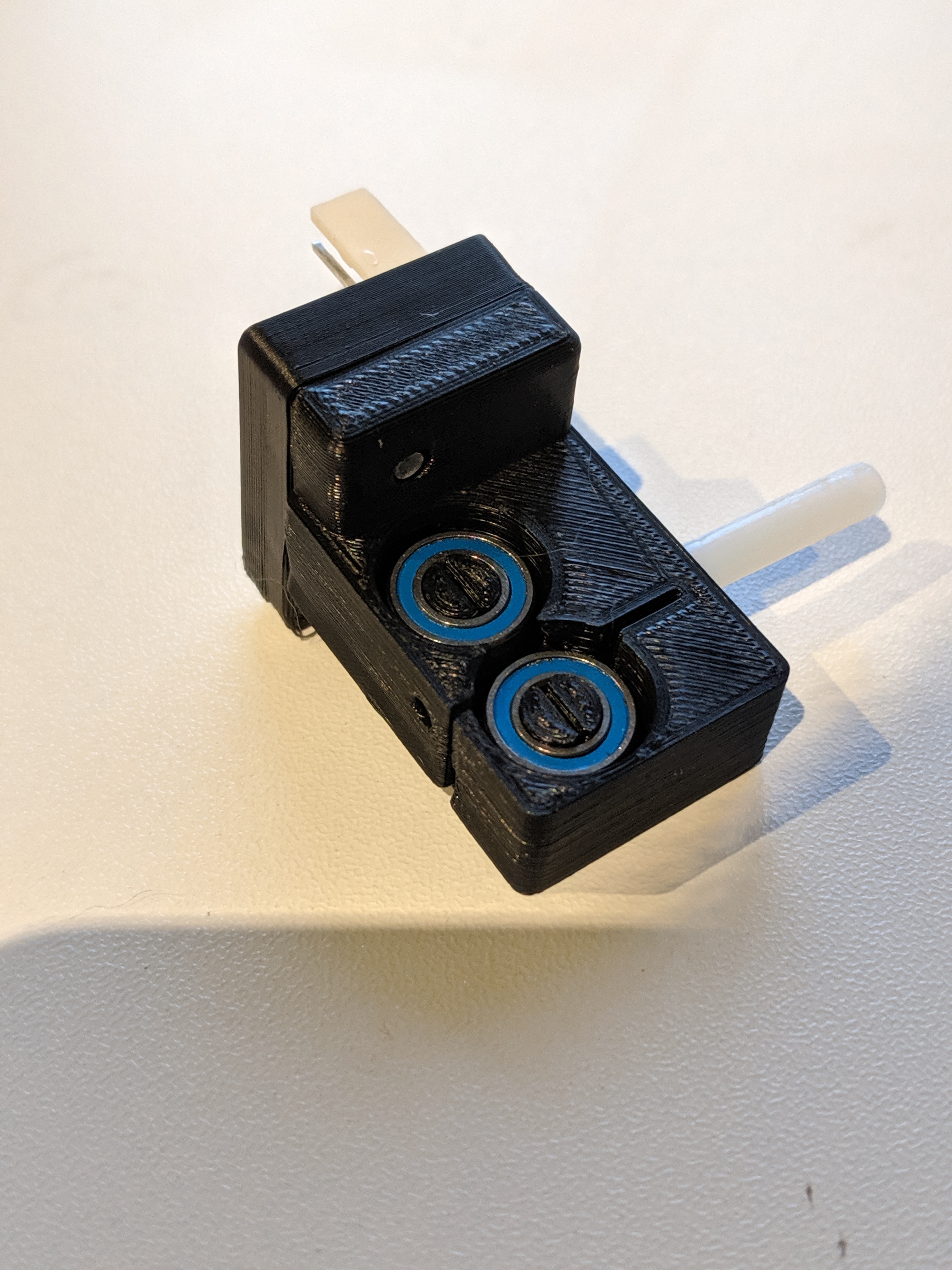
Wasnt sure if I should start a new thread, hopefully its ok just to add here, I printed the concept above from brunofporto with the latest changes by adrian52.. but I don't have the right bearings on hand to properly test. Was going to take a while for bearings to get delivered..
So I decided to have a go at trying to come up with my own design. The goal was to use some decent quality bearings I had on hand - 5x10x4 (mr105) and because I figured it would be something I would be printing different version of, something that was quick & easy to assemble.
So here's my attempt:

I have tried various sensor to bearing surface distances so far.. and I'm finding that around 9mm seems to be the most consistent.
Here is a output from a recent print:

So far it seems to work really well - quite similar to adrian52's results. If you normalise the raw average figure of 299 to be 1 (or 100%) then the lowest reading is 0.956 (4.5% below the average) and the highest reading is 1.023 (2.3% above the average.
I have short tube of around 25mm between the sensor and my extruder input.. so I have set the check to be every 5mm instead of the 3mm in the example which still allows plenty of time to pause the printer if there is an issue, but the slightly longer check also seems to help a bit with consistency.
I have put my stl's and .scad file on thingiverse for anyone to use/mod/try
-
@crash69 Loved your solution for the barings holder!!!!! These bearings are easier to find around here and also cheaper. I'll buy them ASAP and test your design.
 Thanks!
 -
I have been continuing to play with the monitor, and have also made a version for 10mm bearings - I have put it on thingiverse, 3717158. I have made the jaws part spring loaded, so that you can adjust the tension gripping the filament.
When printing slowly, the maximum and minimum values are very accurate (within 2-5%, as above). With faster extrusion, the range tends to get bigger. Using longer measuring intervals seems to give less variation - I am currently using 10mm. Using the A1 switch seem to give a very accurate measure of the total filament used - sometimes giving uncanny agreement with the value reported by DWC (my last print the monitor reported 1640mm, DWC 1639mm, and the slicer said 1643mm). When I use the A0 switch, the monitor reports 85-90% of the filament usage reported by DWC. The total usage data seems to remain extremely accurate when printing faster, where the maximum and minimum values become very wide. Could the max/min variation be due to hitting limits of processing the data? -
It could be that the synchronisation in firmware between the filament sensor reading and the extrusion commanded isn't always working properly.
-
@dc42 have done some more tests using a 20x20x4mm cube with 100%fill, printed at 60mm /sec, then varying the layer height or width to achieve specific filament movement rates. I print the first layer at 10mm/sec, so checking after 100 mm gives a 'slow' baseline for each test, and the total is a little over 700mm. Under these conditions I have no hiccups or missed steps.
For me, the monitor works well with filament movements up to 1.3mm/sec (max/min within 10% of the average) , but for 1.5mm/sec and 2mm/sec, the max/min range becomes very wide, often going negative on the min side. I get similar results with and without a 5mm spacer, although the actual numbers are higher with the spacer as previously observed.
The total extrusion reported by the monitor is very close (usually within 1%) to that shown by dwc or the slicer, even when the extrusion rate is above 1.5mm /sec.
I have also started to note the error rates for the monitor reported by M122. For tests below 1.3mm/sec, frame errors are 2000-4000, and pol errors high(20000-30000). Above 1.3mm/sec, frame errors are 20000 - 30000, but pol errors are below 10000. I have also noticed that the error count is not zeroed when you start a new print - I have been doing a reset after each test to zero things up. -
@adrian52, what is that you are trying to achieve? If it's the detection of filament grinding, do you need exact measurements or just no movement in a certain time period?