Inverting PS_ON levels
-
I've recently wired up one of those PSUs with an inline logic inverter, which I had from a radio control plane, connected to the PS_ON. I reckon your plan should work. The rpi will need to connect the RC+ on the PSU to ground/RC- to turn off the PSU. RC+ can float open circuit or be connected to the +5v standby to enable the PSU. The PSU labelling is confusing, but think of RC+ as the signal wire to switch, RC- as ground, and +5v as +5v. The only problem I can think of is that the standby 5v only supplies 500mA - that might not be enough to power the duet and rpi....
-
@insertnamehere said in Inverting PS_ON levels:
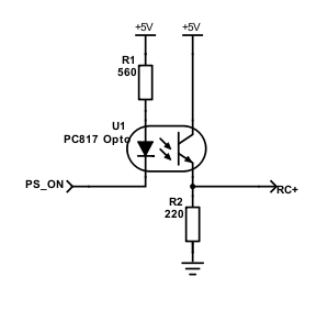
I have a Meanwell supply with an optocoupler and a couple of resistors to invert PS_ON.
If you're handy with a soldering iron it's another possible solution.Soldering is not an issue, how did you make a resistor based inverter?
@pawprinter said in Inverting PS_ON levels:
I've recently wired up one of those PSUs with an inline logic inverter, which I had from a radio control plane, connected to the PS_ON. I reckon your plan should work. The rpi will need to connect the RC+ on the PSU to ground/RC- to turn off the PSU. RC+ can float open circuit or be connected to the +5v standby to enable the PSU. The PSU labelling is confusing, but think of RC+ as the signal wire to switch, RC- as ground, and +5v as +5v. The only problem I can think of is that the standby 5v only supplies 500mA - that might not be enough to power the duet and rpi....
I have a separate 5V PSU wired, so that will be a non issue.
-
@nxt-1 +5V is from the Meanwell aux supply.
-
@insertnamehere are the 5V @ 500mA (says 300mA in the datasheet) enough to power the Duet reliably?
-
@devleon In the OPs case possibly not. I'm using a Meanwell HFG600 which is 5V @ 500mA in the spec.
I don't have a panelDue attached and fans all run off the 24V.
I've seen no problems using a 500mA supply over 100s of hours printing. -
@insertnamehere said in Inverting PS_ON levels:
@nxt-1 +5V is from the Meanwell aux supply.
I'm sorry to dig up this old thread, but I finally can to actually using this schematic. According to the datasheet, the 24V PSU needs: "RC+/RC- : 4 ~10V or open = power on ; 0 ~ 0.8V or short = power off" as a remote control signal. I soldered the little circuit together, but when I connect +5V and GND to the two terminals of my 5V PSU and measure the RC+ output of this diagram, I measure just 3.3V to GND. Also did you leave RC- floating or tied to GND in your printer?
While thinkering with the optocouper, I came to think if there is any good reason to not connect the transistor straight across the RC+ and RC- terminals? As I see it, this would create a short or open based on PS_ON controlling the PSU just as well as a voltage applied. If I am mistaken, please correct me
")
-
@nxt-1 said in Inverting PS_ON levels:
While thinkering with the optocouper, I came to think if there is any good reason to not connect the transistor straight across the RC+ and RC- terminals? As I see it, this would create a short or open based on PS_ON controlling the PSU just as well as a voltage applied. If I am mistaken, please correct me
Yes, I think this is the way to go.
-
Could someone check if RC- is the same as GND of the output?
-
@fma said in Inverting PS_ON levels:
Could someone check if RC- is the same as GND of the output?
I measure 193mV between RC- and V- of my HPRG200-24.
-
I had the same problem and solved it with a simple 7400 NAND gate chip: https://forum.duet3d.com/topic/412/inverting-ps_on
-
So, you wired RC- to GROUND?
-
@tomasf said in Inverting PS_ON levels:
I had the same problem and solved it with a simple 7400 NAND gate chip: https://forum.duet3d.com/topic/412/inverting-ps_on
Mind sketching up a quick diagram?
-
@fma said in Inverting PS_ON levels:
@nxt-1 said in Inverting PS_ON levels:
While thinkering with the optocouper, I came to think if there is any good reason to not connect the transistor straight across the RC+ and RC- terminals? As I see it, this would create a short or open based on PS_ON controlling the PSU just as well as a voltage applied. If I am mistaken, please correct me
Yes, I think this is the way to go.
I tried it, but I forgot the signal needed to be inverted. As a result, this way it is functional but reversed. I not proficient enough with electronics to know if there is anything I can do to fix this, with the stuff I got laying around.

-
This post is deleted! -
Sorry, I've not been online to answer earlier.
I leave RC- open and just connect to the RC+ input.
Are you using the 5V aux from the Meanwell or a separate 5V supply? -
@fma said in Inverting PS_ON levels:
@nxt-1 said in Inverting PS_ON levels:
While thinkering with the optocouper, I came to think if there is any good reason to not connect the transistor straight across the RC+ and RC- terminals? As I see it, this would create a short or open based on PS_ON controlling the PSU just as well as a voltage applied. If I am mistaken, please correct me
Yes, I think this is the way to go.
Hmmm.... let me check.
TO TURN ON SUPPLY.
Duet PS_ON goes to ground to turn on power. PS_ON ground will turn on the opto diode.
Opto diode on will cause the transistor to go ~ short. Short on Meanwell RC+ to RC- will turn OFF the Meanwell supply.If you connect emitter/collector of the opto across the RC+ and RC- of the supply this will not invert the PS_ON signal. That is why the emitter resistor is needed.
-
@nxt-1 said in Inverting PS_ON levels:
@fma said in Inverting PS_ON levels:
@nxt-1 said in Inverting PS_ON levels:
While thinkering with the optocouper, I came to think if there is any good reason to not connect the transistor straight across the RC+ and RC- terminals? As I see it, this would create a short or open based on PS_ON controlling the PSU just as well as a voltage applied. If I am mistaken, please correct me
Yes, I think this is the way to go.
I tried it, but I forgot the signal needed to be inverted. As a result, this way it is functional but reversed. I not proficient enough with electronics to know if there is anything I can do to fix this, with the stuff I got laying around.
This will not invert the PS_ON signal. The PS_ON signal from the Duet is a "Ground = On" and the Meanwell is "Open = On". The Emitter resistor inverts the signal.
-
Yes, you're right. You need to use @jv43 config, using 5V from Meanwell. So this only works for this power supply. If the 5V is from another source, and this source turns off, the Meanwell remains ON

-
@insertnamehere said in Inverting PS_ON levels:
Sorry, I've not been online to answer earlier.
I leave RC- open and just connect to the RC+ input.
Are you using the 5V aux from the Meanwell or a separate 5V supply?I am using a separate 5V Meanwell supply.
@fma said in Inverting PS_ON levels:
Yes, you're right. You need to use @jv43 config, using 5V from Meanwell. So this only works for this power supply. If the 5V is from another source, and this source turns off, the Meanwell remains ON
The other 5V supply is permanently on.
-
@insertnamehere said in Inverting PS_ON levels:
@fma said in Inverting PS_ON levels:
@nxt-1 said in Inverting PS_ON levels:
While thinkering with the optocouper, I came to think if there is any good reason to not connect the transistor straight across the RC+ and RC- terminals? As I see it, this would create a short or open based on PS_ON controlling the PSU just as well as a voltage applied. If I am mistaken, please correct me
Yes, I think this is the way to go.
Hmmm.... let me check.
TO TURN ON SUPPLY.
Duet PS_ON goes to ground to turn on power. PS_ON ground will turn on the opto diode.
Opto diode on will cause the transistor to go ~ short. Short on Meanwell RC+ to RC- will turn OFF the Meanwell supply.If you connect emitter/collector of the opto across the RC+ and RC- of the supply this will not invert the PS_ON signal. That is why the emitter resistor is needed.
I tried the schematic you posted for your HFG600, that supply needs 2 ~ 5V or Open circuit to power on. In this case the ~3.3V I measured from your circuit is perfect. The HPRG I use needs 4 ~ 10V, to turn on, making the 3.3V insufficient. That is why my earlier test failed I believe.