Tool changer actuator endstop.
-
I am having an issue using E0, or E1 endstops as the endstop for my tool changer actuator. They show up as triggered but they aren't, even when there are no endstops hooked to them they show up as triggered. I currently have it plugged into the E0 endstop since I am not using any filament runout sensors.
When i hook my endstop to them nothing happens.
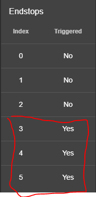
M119 shows this

I had everything working fine a few weeks ago but I had disabled my U axis in the config for a while while I was doing some prints. I come back and re-enable U and the endstop for U will not work. All others work fine. I have even tried attaching a different endstop switch to make sure that it was not a faulty switch and get the same results.
Board: Duet WiFi 1.0 or 1.01 + DueX5
Firmware: RepRapFirmware for Duet 2 WiFi/Ethernet 2.04 (2019-11-01b1)
Duet WiFi Server Version: 1.23
Duet Web Control 2.0.4;General preferences*******************************************************************
G90 ; Send absolute coordinates...
M83 ; ...but relative extruder moves
M550 P"BOXX" ; set printer nameM584 U9 ; tool lock actuator Drive mapping
;Z-Probe*******************************************************************
M307 H7 A-1 C-1 D-1 ; Disable heater on PWM channel for BLTouch
M558 P9 F100 H5 R0.2 T6000 B0 ; Set Z probe type to BLTouch and the dive height + speeds
G31 P25 X-3 Y-39.3 Z0.45 ; Set Z probe trigger value, offset and trigger height
M557 X15:350 Y20:276 S20 ; Define mesh grid;Drives*******************************************************************
M584 X0 Y1 Z2:3 E4:5 ; Drive mappingM569 P0 S0 ; X Drive 0 goes forwards
M569 P1 S1 ; Y Drive 1 goes backwardsM569 P2 S1 ; Z1 Drive 2 goes backwards
M569 P3 S1 ; Z2 Drive 3 goes backwardsM569 P4 S0 ; E0 Drive 4 goes forwards
M569 P5 S0 ; E1 Drive 5 goes forwards
;M569 P6 S0 ; NOT USED;M569 P7 S0 ; NOT USED
;M569 P8 S0 ; NOT USED
M569 P9 S0 ; U Drive 4 goes forwardsM669 K1 ; Select CoreXY mode
M350 X16 Y16 Z16 E16:16 U4 I1 ; Configure microstepping with interpolation
M92 X66 Y66 Z1600 E443.62:443.62 U200 ; Set steps per mmM566 X200 Y200 Z300 E1000:1000 U100 ; Set maximum instantaneous speed changes (Jerk) (mm/min)
M203 X30000 Y30000 Z400 E4000:4000 U5000 ; Set maximum speeds (mm/min)
M201 X800 Y800 Z80 E1000:1000 U800 ; Set accelerations (mm/s^2)M906 X1200 Y1200 Z1300 E400:600 U1200 I30 ; Set motor currents (mA) and motor idle factor in percent
M84 S30 ; Set idle timeout;Heaters*******************************************************************
M305 P0 S"BED" T100000 B4138 C0 ; Set thermistor
M143 H0 S100 ; Set temperature limit for heater 0 to 225CM305 P1 R4700 T100000 B4388 ; Set thermistor
M143 H1 S280 ; Set temperature limit for heater 3 to 300C
M307 H1 A934.7 C268.4 D7.9 V24.1 ; Set PID parameters for heater 1M305 P2 R4700 T100000 B4388 ; Set thermistor
M143 H2 S280 ; Set temperature limit for heater 4 to 300C
M307 H2 A796.6 C254.5 D8.6 V24.1 ; Set PID parameters for heater 2;Tools*******************************************************************
M563 P0 D0 H1 F4 ; Define tool 0
G10 P0 X0 Y0 Z0 ; Reset tool 0 axis offsets
G10 P0 R0 S0 ; Reset initial tool 0 active and standby temperatures to 0CM563 P1 D1 H2 F6 ; Define tool 1
G10 P1 X0 Y0 Z0 ; Reset tool 1 axis offsets
G10 P1 R0 S0 ; Reset initial tool 1 active and standby temperatures to 0C;Fans*******************************************************************
;M106 P0 S0 I0 F500 H-1 ; UNUSED
M106 C"T0 FAN" P3 S1 I0 F500 H1 T70 ; T0 HE
M106 C"T0 LAY FAN" P4 S0 ; T0 PCF
M106 C"T1 FAN" P5 S1 I0 F500 H2 T70 ; T1 HE
M106 C"T1 LAY FAN" P6 S0 ; T1 PCF
;M106 P7 S0 H3 T70 ; T2 HE
;M106 P8 S0 ; T2 PCF;Axis Limit*******************************************************************
M208 X0:355 Y0:360 Z0:400 ; Set axis min/max
M208 U0:300 ; Set axis min/max;Endstop Settings*******************************************************************
M574 Z1 S2 ; Set endstops controlled by probe
M574 X1 Y1 S1 ; Set active high endstops
M574 U1 S1 ; Set homing switch configuration for toolchange lock. Both switches should be wired NC and in series.;Resume after power loss*******************************************************************
M911 S21.0 R23.0 P"M913 X0 Y0 G91 M83 G1 Z3 E-5 F1000" -
Perhaps what I don't understand is how the cofig knows which endsop goes with which drive.
-
@cdl1701yahoo-com said in Tool changer actuator endstop.:
Perhaps what I don't understand is how the cofig knows which endsop goes with which drive.
Using M584 to map drivers to axes does not affect endstop inputs. Endstop inputs XYZ are pre-allocated, after that they are allocated in the order in which axes are created. So if you create just one extra axes (e.g. U), it will use the E0 endstop input. If more than one axis is created in a single M584 command, endstop inputs are allocated to the new axes in that command in the order UVWABC.
In RRF3 the endstops are definable.
-
UPDATE
Not sure what is going on but after a few days of taking a break I decided to get back to working on this and now the U endstop works! My config is still exactly the same as it was above.. so confused.. anyway now on to the next issue!
-
if you didn't change the config, odds are the wiring is not 100%.
-
@cdl1701yahoo-com RepRapFirmware also creates endstops for defined tools, of which you have two. So your endstops as reported by DWC are X=0 (connected to X_STOP), Y=1 (connected to Y_STOP), Z=2 (connected to Z_STOP), U=3 (connected to E0_STOP, the next physical connection available), T0=4 and T1=5 (both not defined/connected).
I agree with @bearer, probably dodgy U endstop wiring!
Ian
-
 There needs to be a banging head against the wall emoji. So I have been fine tuning everything tonight and getting my tool offsets set up when all of a sudden this endstop problem pops up again. The endstop says that it is triggered but isn't so when I try to use the tool lock it thinks it is already at the endstop. Even when I replace the endstop with a new one it does the same thing...!!!
 -
Was the wiring replaced as well? Does the wiring run alongside other wiring?
-
@cdl1701yahoo-com Can you Post a picture of your setup? Maybe it is a mechanical or wiring problem...
-
Turned the machine on and it is working again...
@droftarts Yes, I have a test endstop that I use that has its own wire and I can activate it manually with my hand. That one works fine for the X & Y but not on any of the Estops. This printer does some strange things sometimes just randomly so I am wondering if it is the board.. it is quite old and has who knows how many hours of run time on it.@Phaedrux it runs seperate from any of the high voltage wires and the stepper wires so I would not think that it would be getting interference but I guess it is possible?
Anyway, it is working for now again so back to fine tuning.
-
@cdl1701yahoo-com said in Tool changer actuator endstop.:
it is quite old and has who knows how many hours of run time on it.
I’m still using one of the white PCB beta Duet WiFi boards! However, it didn’t get much use, until I installed it this summer on an old printer to run as a testbed. Tony told me there aren’t many left, as most were tested to destruction!
Ian
-
This one I think is about 3-4 year old and has been running since then but it is not a white one. I do have some stepper motor cables that run over the top of the board, I an thinking tomorrow that I will re-route those to have them go around the board rather than over it and see if that helps.
So far though has been running all day with no issues.