Duet3D Logo Duet3D
    • Tags
    • Documentation
    • Order
    • Register
    • Login

    Dual Y Motor Configuration

    Scheduled Pinned Locked Moved
    General Discussion
    6
    39
    3.2k
    Loading More Posts
    • Oldest to Newest
    • Newest to Oldest
    • Most Votes
    Reply
    • Reply as topic
    Log in to reply
    This topic has been deleted. Only users with topic management privileges can see it.
    • dc42undefined
      dc42 administrators @3DPrintingWorld
      last edited by

      @3DPrintingWorld said in Dual Y Motor Configuration:

      I got sensorless homing to work but the dual y axis motors are still tied together. What am I missing?

      What exactly do you mean? The motors should indeed be tied together, except that when homing them they should stop individually as they stall. Bear in mind that when one motor stall, the other will be moving the carriage by itself; so the load on it will increase, and if the stall threshold is set too low then it may report a stall immediately.

      Duet WiFi hardware designer and firmware engineer
      Please do not ask me for Duet support via PM or email, use the forum
      http://www.escher3d.com, https://miscsolutions.wordpress.com

      3DPrintingWorldundefined 1 Reply Last reply Reply Quote 0
      • 3DPrintingWorldundefined
        3DPrintingWorld @dc42
        last edited by

        @dc42 It seems to work well but one side is not making contact with the frame. Both motors seem to stall at the same time. I see what you are saying about the increased load on the other motor. If I turn the threshold up the belts start skipping before the other end makes contact with the frame. I have the motors turned down to 30%, do I need to increase the speed with the threshold? The thing is, It really does not take much torque to skew the frame which is why I'm relying on the motors to keep it square.

        Seems like I have something wrong with the programming. Is my M915 command right in my Homey script? It knows that "Y" is two motors.

        dc42undefined droftartsundefined 2 Replies Last reply Reply Quote 0
        • dc42undefined
          dc42 administrators @3DPrintingWorld
          last edited by

          @3DPrintingWorld said in Dual Y Motor Configuration:

          If I turn the threshold up the belts start skipping before the other end makes contact with the frame

          Are you sure that is it possible for the second motor to carry on turning, without the axis binding and that causing a stall?

          Duet WiFi hardware designer and firmware engineer
          Please do not ask me for Duet support via PM or email, use the forum
          http://www.escher3d.com, https://miscsolutions.wordpress.com

          3DPrintingWorldundefined 2 Replies Last reply Reply Quote 0
          • droftartsundefined
            droftarts administrators @3DPrintingWorld
            last edited by

            @3DPrintingWorld What firmware are you on? You need to be on RRF 3 for this to work properly as you have it set up at the moment, not RRF 2. Send M115 at the console, and post reply.

            Ian

            Bed-slinger - Mini5+ WiFi/1LC | RRP Fisher v1 - D2 WiFi | Polargraph - D2 WiFi | TronXY X5S - 6HC/Roto | CNC router - 6HC | Tractus3D T1250 - D2 Eth

            3DPrintingWorldundefined 1 Reply Last reply Reply Quote 0
            • 3DPrintingWorldundefined
              3DPrintingWorld @dc42
              last edited by

              @dc42 I think you might be right! The attached picture shows the belt arrangement. Maybe the X and U axis's are keeping the X-axis from twisting. I will try taking the second motor(P9) out of the config and see if I can move it with my finger after its been homed.

              I do see an issue that the x(u) carriage must be away from the switch(end of travel) when homing the Y otherwise when the Y motor stalls the x(u) carriage will be pulled into the switch. My plan for home all was to home X & U first then move them away from their switch before homing the Y.

              Is it possible to turn the x and u axis off the moment the Y detects a stall?

              BELT ASSY.png

              1 Reply Last reply Reply Quote 0
              • 3DPrintingWorldundefined
                3DPrintingWorld @droftarts
                last edited by

                @droftarts Yep, I just switched to RRF 3 last night. I can do this when I get home but I think the issue may be that the belt arrangement is keeping the x axis from twisting. I will confirm both tonight.

                1 Reply Last reply Reply Quote 0
                • 3DPrintingWorldundefined
                  3DPrintingWorld @dc42
                  last edited by

                  @dc42 I tried multiple things, I can verify that the issue was not that the motor could not turn. I ended up getting it to work once I turned up the motor current to 50%. If I turned that up any more or the S value I would get skipping. The first time its homed and its far out of skew the farthest side does not always make contact. Then by the second or third time it always makes contact but has the tendency to bounce off.

                  I think I'm just going to add a second switch to the Y axis and hopefully call it a day.

                  botundefined 1 Reply Last reply Reply Quote 0
                  • botundefined
                    bot @3DPrintingWorld
                    last edited by

                    @3DPrintingWorld

                    That's an interesting belt arrangement. Is the reason you did not drive the Y axis from one motor because you couldn't get a belt long enough to go around the whole way?

                    *not actually a robot

                    3DPrintingWorldundefined 1 Reply Last reply Reply Quote 0
                    • 3DPrintingWorldundefined
                      3DPrintingWorld @bot
                      last edited by

                      @bot No not really, I debated a few different arrangements but decided this one was the best and I had a extra driver on the duex5. Less maintenance, setup and believe it or not probably the cheapest option out of the four. If you are interested I have been posting pictures of my progress on my twitter.

                      !Y-AXIS.PNG

                      droftartsundefined 1 Reply Last reply Reply Quote 0
                      • droftartsundefined
                        droftarts administrators @3DPrintingWorld
                        last edited by

                        @3DPrintingWorld interesting layout! I’m considering something similar for my current build, but single carriage and tool changer. See https://forum.duet3d.com/post/118078

                        Ian

                        Bed-slinger - Mini5+ WiFi/1LC | RRP Fisher v1 - D2 WiFi | Polargraph - D2 WiFi | TronXY X5S - 6HC/Roto | CNC router - 6HC | Tractus3D T1250 - D2 Eth

                        3DPrintingWorldundefined 1 Reply Last reply Reply Quote 0
                        • botundefined
                          bot
                          last edited by

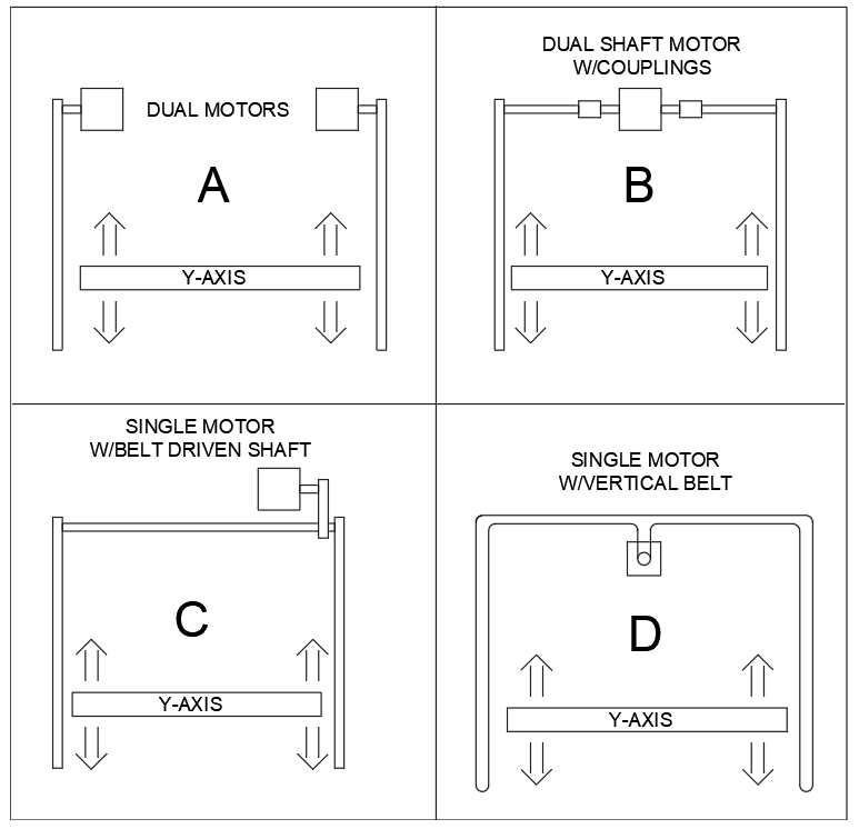
                          What would make the single motor setup more costly? It seems with the difficulty of synchronizing the motors taken into account, it may be easier to do a single motor if the belt is not too long.

                          *not actually a robot

                          3DPrintingWorldundefined 1 Reply Last reply Reply Quote 0
                          • 3DPrintingWorldundefined
                            3DPrintingWorld @droftarts
                            last edited by

                            @droftarts That looks really cool, your extruders look sweet! What keeps your x-axis from skewing. I know without the y-axis belts on the current setup I have the x-axis would be all over the place.

                            droftartsundefined 1 Reply Last reply Reply Quote 0
                            • 3DPrintingWorldundefined
                              3DPrintingWorld @bot
                              last edited by

                              @bot An additional stepper motor is only like $15, versus a shaft, couplings, and a couple bearings. I guess if you went with version "D" it might be cheaper, depending on the belt.

                              Its taking me a little bit to get the homing right but I think it will be the right choice in the long run.

                              1 Reply Last reply Reply Quote 0
                              • droftartsundefined
                                droftarts administrators @3DPrintingWorld
                                last edited by

                                @3DPrintingWorld pictures aren’t mine, they’re from the RepRap forums link. The ‘double’ markforge layout is basically a CoreXY, just with the idler that usually takes the belts across the top of the frame moved to the X axis. So it’s in balance, just like a CoreXY, unlike an Hbot or single-sided Y Markforge. It’s effectively yours without the Y axis belts and motors, and with one X carriage the joins the two belts, rather than having them independent.

                                Ian

                                Bed-slinger - Mini5+ WiFi/1LC | RRP Fisher v1 - D2 WiFi | Polargraph - D2 WiFi | TronXY X5S - 6HC/Roto | CNC router - 6HC | Tractus3D T1250 - D2 Eth

                                3DPrintingWorldundefined 1 Reply Last reply Reply Quote 0
                                • 3DPrintingWorldundefined
                                  3DPrintingWorld @droftarts
                                  last edited by

                                  @droftarts Let me know how it works out when you get it done!

                                  1 Reply Last reply Reply Quote 0
                                  • 3DPrintingWorldundefined
                                    3DPrintingWorld
                                    last edited by

                                    Well, I'm not having much luck figuring out anything on my own.... I'm trying to add a second endstop to the y-axis. With one switch its working fine. When I add "+e1stop" to the M574, if either switch is touched it switches the ystop and both motors stop. What am I doing wrong here? Or do I need to add something to my homey to home two motors on a single axis?

                                    M584 X0 U2 Y1:9 Z5:6:7 E3:4

                                    M574 X2 S1 P"xstop"
                                    M574 Y2 S1 P"ystop+e1stop"
                                    M574 U1 S1 P"e0stop"

                                    3DPrintingWorldundefined 1 Reply Last reply Reply Quote 0
                                    • 3DPrintingWorldundefined
                                      3DPrintingWorld @3DPrintingWorld
                                      last edited by

                                      @dc42 I was wondering if you could help me with this. I have two switches for the y-axis now. When I configure it like this all switch indicate properly in the endstops status screen.
                                      M574 X2 S1 P"xstop" ; X min active high endstop switch
                                      M574 Y2 S1 P"zstop" ; Y min active high endstop switch
                                      M574 U1 S1 P"e0stop" ; U max active high endstop switch

                                      But when I add the second endstop tag to the y axis like below the ystop switch no longer changes state only the zstop switch.

                                      M574 X2 S1 P"xstop" ; X min active high endstop switch
                                      M574 Y2 S1 P"ystop+zstop" ; Y min active high endstop switch
                                      M574 U1 S1 P"e0stop" ; U max active high endstop switch

                                      Can you enlighten me to what I am doing wrong. The other odd thing is when I unplug the zstop and remove its tag from the config, it shows as triggered. Shouldn't that be the opposite?

                                      1 Reply Last reply Reply Quote 0
                                      • dc42undefined
                                        dc42 administrators
                                        last edited by

                                        @3DPrintingWorld, which firmware version are you running? Send M115 to confirm it.

                                        Please post your complete config.g file and homing files.

                                        Duet WiFi hardware designer and firmware engineer
                                        Please do not ask me for Duet support via PM or email, use the forum
                                        http://www.escher3d.com, https://miscsolutions.wordpress.com

                                        3DPrintingWorldundefined 1 Reply Last reply Reply Quote 0
                                        • 3DPrintingWorldundefined
                                          3DPrintingWorld @dc42
                                          last edited by

                                          @dc42 RRF 3.0

                                          G90                                             ; send absolute coordinates...
                                          M83                                             ; ...but relative extruder moves
                                          
                                          M669 K0 Y1:-1:0:1				; select Markforged Kinematics Y to react with X and U
                                          
                                          ; Axis Limits
                                          M208 X35 Y0 U-18.4 Z0 S1                        ; set axis min
                                          M208 X419 U365 Y336 Z300 S0                     ; set axis max
                                          
                                          ; Network
                                          M552 S1                                         ; enable network
                                          M586 P0 S1                                      ; enable HTTP
                                          M586 P1 S0                                      ; disable FTP
                                          M586 P2 S0                                      ; disable Telnet
                                          
                                          ; Drives
                                          M569 P1 S0                                      ; X physical drive 0 goes backwards
                                          M569 P1 S1                                      ; Y right physical drive 1 goes forwards
                                          M569 P2 S0                                      ; U physical drive 2 goes backwards
                                          M569 P3 S1                                      ; E1 physical drive 3 goes forwards
                                          M569 P4 S1                                      ; E2 physical drive 4 goes forwards
                                          M569 P5 S0                                      ; Z left physical drive 5 goes backwards
                                          M569 P6 S0                                      ; Z center physical drive 6 goes backwards
                                          M569 P7 S1                                      ; Z right physical drive 7 goes forwards
                                          M569 P9 S0                                      ; Y left physical drive 8 goes backwards
                                          M584 X0 U2 Y1:9 Z5:6:7 E3:4                     ; set drive mapping
                                          
                                          M350 X16 U16 Y16 Z16 E16:16 I1                  ; configure microstepping with interpolation
                                          M92 X100.00 U100.00 Y100.00:80.00 Z1096:1096:1096 E1827.00:1827.00       ; set steps per mm
                                          M566 X900.00 U900.00 Y900.00:900.00 Z12.00:12.00:12.00 E40.00:40.00      ; set maximum instantaneous speed changes (mm/min)
                                          M203 X6000.00 U6000.00 Y6000.00:6000.00 Z1000.00:1000.00:1000.00 E1800.00:1800.00 ; set maximum speeds (mm/min)
                                          M201 X500.00 U500.00 Y500.00:500.00 Z20.00:20.00:20.00 E120.00:120.00      ; set accelerations (mm/s^2)
                                          M906 X800 U800 Y800:800 Z200:200:200 E500:500 I30                ; set motor currents (mA) and motor idle factor in per cent
                                          M84 S30                                         ; Set idle timeout
                                          
                                          ; Endstops
                                          M574 X2 S1 P"xstop"                             ; X max active high endstop switch
                                          M574 U1 S1 P"e0stop"                            ; U min active high endstop switch
                                          M574 Y2 S1 P"ystop"                             ; Y max active high endstop switch
                                          ;M574 Y2 S1 P"ystop+zstop"                      ; Y Double max active high endstop switch
                                          
                                          ; Z-Probe
                                          M671 X-20.6:200:420.6 Y14.3:333.3:14.3 S2       ;Locations left, center, right          
                                          M950 S0 C"duex.e6heat"                          ; create servo pin 0 for BLTouch
                                          M558 P9 C"zprobe.in+zprobe.mod" H5 F120 T6000   ; set Z probe type to bltouch and the dive height + speeds
                                          G31 P25 X28.8 Y0 Z2.15                          ; set Z probe trigger value, offset and trigger height
                                          
                                          ; Heaters
                                          M308 S0 P"bedtemp" Y"thermistor" T100000 B4534 C9.565227e-8  ; configure sensor 0 as thermistor on pin bedtemp
                                          M950 H0 C"bedheat" T0                                     ; create bed heater output on bedheat and map it to sensor 0
                                          M143 H0 S120                                              ; set temperature limit for heater 0 to 120C
                                          M307 H0 B0 S1.00                                          ; disable bang-bang mode for the bed heater and set PWM limit
                                          M140 H0                                                   ; map heated bed to heater 0
                                          M308 S1 P"e0temp" Y"thermistor" T500000 B4723 C1.19622e-7 ; configure sensor 1 as thermistor on pin e0temp
                                          M950 H1 C"e0heat" T1                                      ; create nozzle heater output on e0heat and map it to sensor 1
                                          M143 H1 S280                                              ; set temperature limit for heater 1 to 280C
                                          M307 H1 B0 S1.00                                          ; disable bang-bang mode for heater  and set PWM limit
                                          M308 S2 P"e1temp" Y"thermistor" T500000 B4723 C1.19622e-7 ; configure sensor 2 as thermistor on pin e1temp
                                          M950 H2 C"e1heat" T2                                      ; create nozzle heater output on e1heat and map it to sensor 2
                                          M143 H2 S280                                              ; set temperature limit for heater 2 to 280C
                                          M307 H2 B0 S1.00                                          ; disable bang-bang mode for heater  and set PWM limit
                                          
                                          ; Fans
                                          M950 F0 C"fan0" Q500                             ; create fan 0 on pin fan0 and set its frequency
                                          M106 P0 S0 H-1                                   ; set fan 0 value. Thermostatic control is turned off
                                          M950 F1 C"fan1" Q500                             ; create fan 1 on pin fan1 and set its frequency
                                          M106 P1 S1 H1 T45                                ; set fan 1 value. Thermostatic control is turned on
                                          M950 F2 C"fan2" Q500                             ; create fan 2 on pin fan2 and set its frequency
                                          M106 P2 S0 H-1                                   ; set fan 2 value. Thermostatic control is turned off
                                          M950 F3 C"duex.fan8" Q500                        ; create fan 3 on pin duex.fan4 and set its frequency
                                          M106 P3 S1 H2 T45                                ; set fan 3 value. Thermostatic control is turned on
                                          
                                          ; Tools
                                          M563 P0 D0 H1 X3 F0 S"Left"                      ; define tool 0 left 
                                          G10 P0 X0 Y-1.2 Z0                               ; set tool 0 axis offsets
                                          G10 P0 R0 S0                                     ; set initial tool 0 active and standby temperatures to 0C
                                          M563 P1 D1 H2 F2 S"Right"                        ; define tool 1 Right
                                          G10 P1 X0 Y0 Z0                                  ; set tool 1 axis offsets
                                          G10 P1 R0 S0                                     ; set initial tool 1 active and standby temperatures to 0C
                                          M563 P2 D0:1 H1:2 X0:3 F0:2 S"Copy"              ; define tool 2 copy
                                          G10 P2 X-75 Y0 U75 S0 R0                         ; set tool 2 axis offsets
                                          M567 P2 E1:1                                     ; set mix ratio 100% on both extruders
                                          
                                          M501                                             ; Record
                                          
                                          ; homeall.g
                                          
                                          ; X,U,Y Homing
                                          G91                         ; relative positioning
                                          G1 H2 Z5 F6000              ; lift Z relative to current position
                                          G1 H1 X475 U-475 Y500 F1800 ; move quickly to X or Y endstop and stop there (first pass)
                                          G1 H1 X475                  ; home X axis
                                          G1 H1 U-475                 ; home U axis
                                          G1 H1 Y500                  ; home Y axis
                                          G1 X-5 U5 Y-5 F6000         ; go back a few mm
                                          G1 H1 X25 F360              ; move slowly to X axis(second pass)
                                          G1 H1 U-25                  ; move slowly to U axis(second pass)
                                          G1 H1 Y25                   ; move slowly to Y axis(second pass)
                                          
                                          ; Z Homing
                                          G90 G1 X171 Y150 F10000      ; Move to the center of the bed
                                          M558 F500                    ; Fast probing speed
                                          G30                          ; First probe
                                          M558 F50                     ; Slow probing speed
                                          G30                          ; Second probe
                                          G32                          ; Level the bed
                                          G90 G1 X171 Y150 F10000      ; Move to the center of the bed
                                          G30                          ; Bed Deviation probe
                                          G90 G1 X417                  ; Park x-axis
                                          
                                          
                                          1 Reply Last reply Reply Quote 0
                                          • First post
                                            Last post
                                          Unless otherwise noted, all forum content is licensed under CC-BY-SA