My CoreXY 500X500X500 duet wifi controlled printer
-
Hello,
I have just got my Core XY printer to a stage where I can now start printing things. I have had a huge help from this forum by just reading about issues relevant to my stage of the printer construction. Just thought I would show some pics of how I went about my design.(https://photos.google.com/photo/AF1QipOCxdsFYbNfOynEF8DJ_eslK6yXvbeizdb9B6g_)
The printer is fully enclosed as I want to print Nylon and CF Nylon which require an enclosure. All of the electronics is therefore external. The Duet wifi and a seven inch PanelDue is in a custom box with all external connectors accessible.([https://photos.google.com/photo/AF1QipPtProFC6gnkE2F4rFxIv4g-gSa9WsLlP5HueQ7))
I started the design with a flexible PEX print surface which I purchased from Wham Bam (I have no links with this company). The build plate is 5mm aluminium sheet (chopped from big sheet by local metal merchant) and I have used a lead screw on each corner paired to be driven by two independant Z motors as I did not want to use an expansion board. There are only two rails for the Z axis and I have used a short rail to connect one end of the build surface to allow for thermal expansion.The plate is heated with 4X200 watt 240V heaters. The plate is mounted on heavy duty springs (home made) to give 9 point bed leveling . The plate has come in better than +/- 50 microns.
https://photos.google.com/photo/AF1QipOi53EVtrkPGIwPXEf1okGsadRf0iDHVKAQJR-t!
I am using a genuine E3D V6 24 V extruder to allow me to print high temperatures. Note the custom cooling shroud with integrated BLtouch mount. https://photos.google.com/photo/AF1QipOjGvtmdMIGpEwgFb4r7VSW8ZvGot_9XeFl7nXJ
I have designed a continuously adjustable tension system for the coreXY belts to allow easy setting of the belt tensions. If the belt tension is not identical the X carriage tends to rack.https://photos.google.com/photo/AF1QipOS5LQaY3V-R69XJoLthSARXXTXbVTnu6sZ3Rkx
I have connect one end of the X carriage via a rail slide to allow for thermal expansion.
The filament out sensor uses a microswitch driven by a simple arm fully adjustable. The filament runs on the head of a 3mm bolt so will not wear in a hurry.
Test prints show that the mechanics are sound. -
Morning,
Getting 404 errors on the links you posted.
Paul
-
Mee too 404
-
Me three
-
Hi,
Posting links on the forum is new to me so obviously not doing the right thing. The photos are on google photos and I just copy and pasted the links associated with the photo. Perhaps it requires some sharing to be activated. Any hints on how to get some working links would be appreciated. When I click on the link it works so difficult for me to chech as an outsider. -
@Willo47 I get a 404 too. I think it’s that the photos are not shared publicly. Check privileges on them.
Ian
-
@Willo47 you could also create a free imgur account and upload them there. This way they would be less prone to link rot as you could clean up your google drive and delete these images by accident. This also avoids sharing your personal google drive albeit only select images.
-
Hi there, I have reduced the size of my pictures and will uploadload them onto the site to solve any further problems.
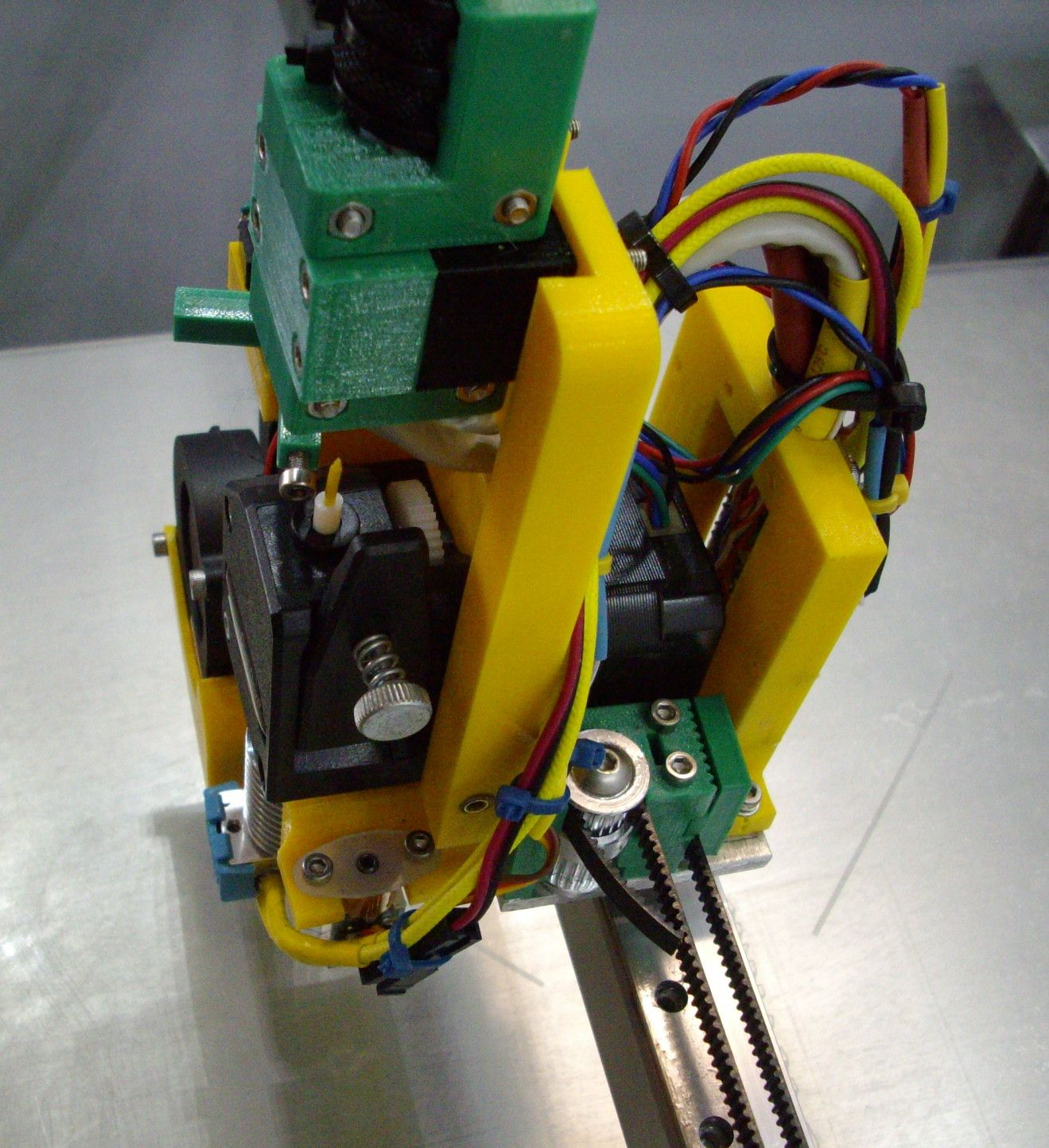 Picture of extruder with continously variable belt tensioner.
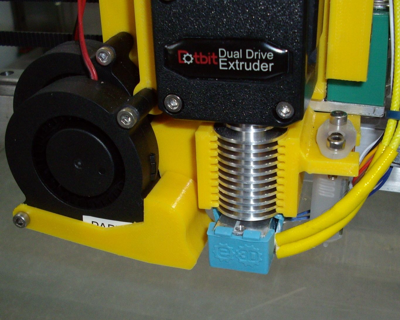
Hotend fan shroud with integrated BL touch mount.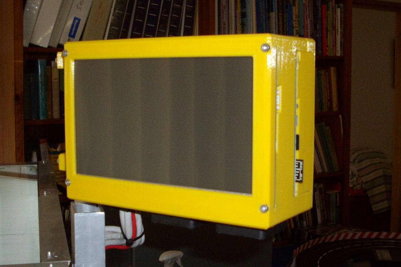
Duet wifi and 7inch panel due case on swivel mount.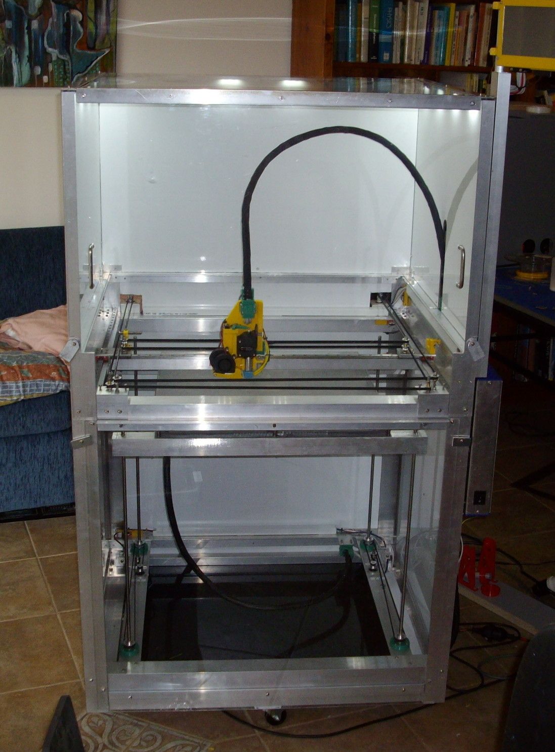
The printer fully enclosed suitable for printing nylon and ABS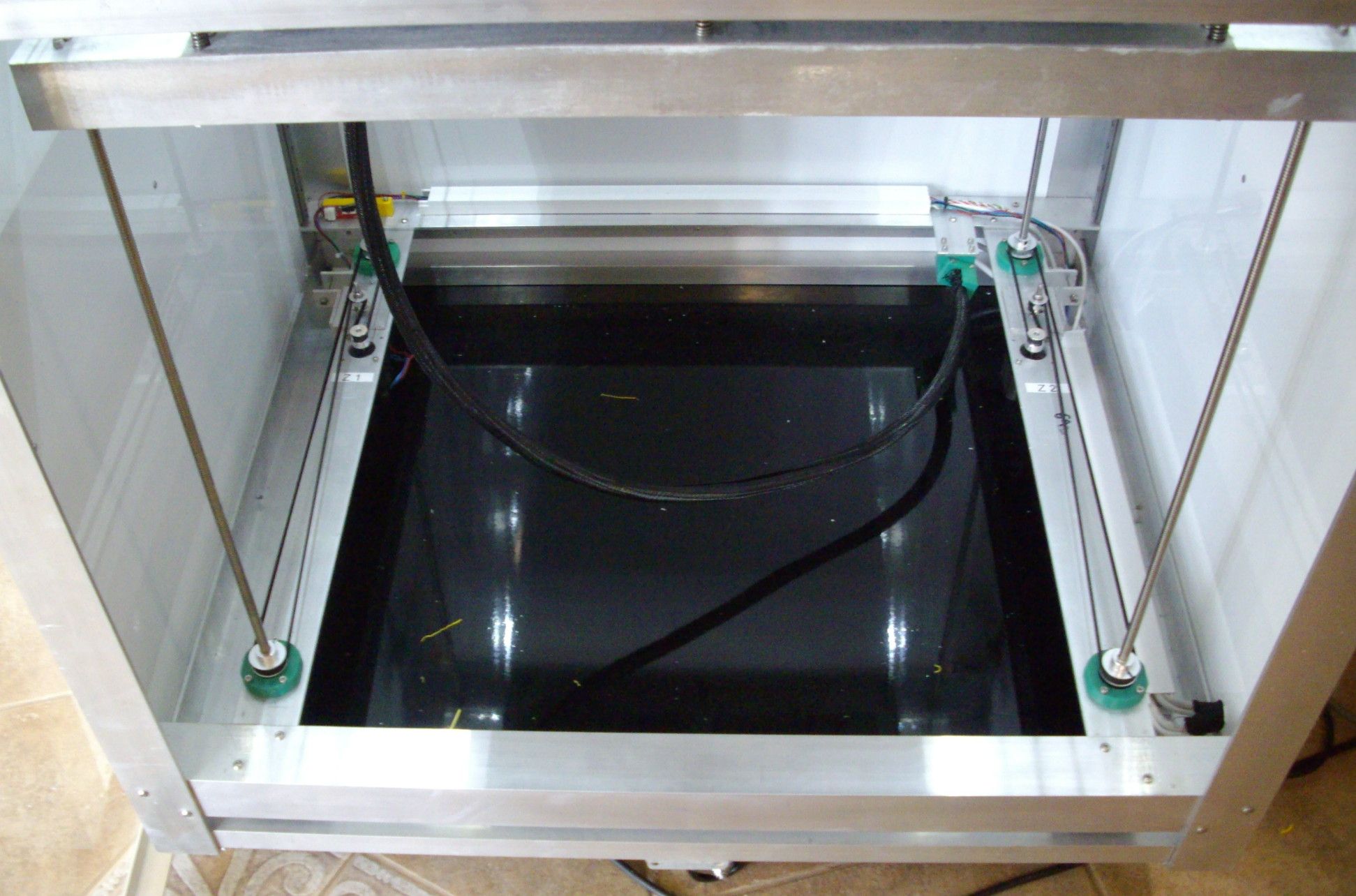
Four lead screws Z mount driven by two independent Z steppers to allow two point bed leveling.Hope this works.
-
Nice

With 4 screws I'd get an duex 5 and have full automatic bed levelling.
I don't see any guides for the bed travelling along Z. No linear rails or rods. What's keeping the bed wobbling with the screws? Or do you have perfect screws?
-
The two rails for the Z axis are on the rear of the frame. I have connected one side of the bed frame via a small (100mm) horzontal rail and a rail slide to allow for thermal expansion. Two rails are sufficient to locate the bed.
-
@Willo47 said in My CoreXY 500X500X500 duet wifi controlled printer:
The two rails for the Z axis are on the rear of the frame. I have connected one side of the bed frame via a small (100mm) horzontal rail and a rail slide to allow for thermal expansion. Two rails are sufficient to locate the bed.
Cool. I can barely make out some rails in the back on both sides.
I just spent 1 hour leveling the bed properly the first time on my new Ender 5 Plus. G32 runs the bed.g file and levels the bed pivot on Y. Then a makro to redefine the config so it gives my how much I have to adjust the 4 corned screws. I think I made 20 passes before I was in the ballpark of less then 0.02 mm on all sides. Every time I adjusted 1-2 screws the other side changed. Probably because there was a lot of tension until you get it all correct. 3 adjustment screws would have been a walk in the park. This is why I would really have 4 steppers for your bed screws. The Duet can do it all for you.
Looking forward to hear how it prints.
-
@Willo47 I love the "continuously variable belt tensioner"
") I'm just in the process of redesigning my tool carriage and am doing the same thing.
I'm just in the process of redesigning my tool carriage and am doing the same thing. -
First reply is re the variable belt tensioner. The system works a treat in that I have the X carriage at the Y max position where it is next to the rear frame where I can get a reference as to if the X carriage is straight. I then tune the tension until the carriage is parallel to the frame and then tighten the nuts underneath.
The picture shows the system with printed parts using PETG. Unfortunately as I use bed temperatures of up to 90deg C this is above the glass temperature of PETG and the plastic tends to give. I have just re-made these components from aluminium which has solved the problem. -
Reply to "Strips" re bed leveling.
My build plate is fitted to a frame which is supported at each of the four corners by the lead screws.
The build plate is supported at 9 points (three at each side and one in the middle) by 4mm threaded rod screwed into the base plate (pre threaded prior to fixing magnetic build plate) and locked with a nut. The bed held off the frame by very stiff compression springs. I made my own using 1.6mm spring steel wire wound on a 5mm mandrel and about 15mm long. The springs need to be stiff enough to be able to bend the 5mm thick build plate a small amount so that any bow can be removed from the plate.
For initial leveling I printed a mount for a dial gauge on the extruder carriage and used that to get it withing +/-50 microns. This saved a lot of time as you can get almost instant indication of how level the bed is.
Once that was done I fitted the extruder and used the BLtouch probe to probe the bed using the via the DWC. Initially I only had 9 points on the mesh which coincided with the bed adjustement points. After each adjustment I did the two point be leveling prior to doing another mesh be leveling probe. It took few itterations to get it level. Once I was happy I then did a 64 point mesh bed grid which I use when doing a print. The final bed leveling is done with the bed heated to 80deg C which I use for the first layer bed temperature for PETG which I am currently printing.
I am currently printing a 400mm 5 spoke test wheel to check out the bed. Looks good so far. -
@Willo47 I can see that a dial gauge would be helpful with 9 points
 Sounds like good engineering!