Keenovo 220v setup
-
Hello
I have a 220v 750w silicone bed from Keenovo wired correctly as seen in on other thread.
I have a correct thermistor reading but when I'm doing PID tuning, the bed doesn't heat.
I have a SSR :RS1a23d25s62 AC51:25amp 240v 3-32v
Where am I wrong ?
ThanksHere is my Heaters config :
; Heaters
M308 S0 P"temp1" Y"thermistor" T95000 B3950 ; configure sensor 0 as thermistor on pin temp1
M950 H0 C"out0" T0 ; create bed heater output on out0 and map it to sensor 0
M307 H0 B0 ; disable bang-bang mode for the bed heater and set PWM limit
M140 H0 S-273.15 ; map heated bed to heater 0
M143 H0 S120 ; set temperature limit for heater 0 to 120C
M308 S1 P"temp0" Y"thermistor" T410000 B4723 C1.19622e-7 ; configure sensor 1 as thermistor on pin temp0
M950 H1 C"out1" T1 ; create nozzle heater output on out1 and map it to sensor 1
M307 H1 B0 S1.00 ; disable bang-bang mode for heater and set PWM limit -
How have you connected the SSR to the Duet? Have you connected the + and - control input wires the right way round?
-
@dc42
Duet3 (out0) instead of Duet2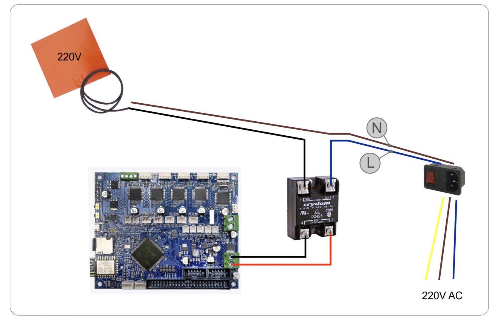
-
Hi,
Did you verify that 220 is present on the L and N wires?
Frederick
-
@fcwilt
No, with a tester ? -
@Touchthebitum said in Keenovo 220v setup:
@fcwilt
No, with a tester ?I was just wondering if that power switch was wired/working correctly. I had one that was defective.
Do you have a device that you can test for power on those wires?
Frederick
-
@fcwilt
No, unfortunately
Sparkcube XL V 1.1 300x300x190, Radds, Raspberry, Keenovo silicone bedheat 220v, Big Booster Extruder, DIY building
BLV Cube 665mm Direct Drive with Duet3/SBC (RPi 4) Mosquito Magnum/Bond Tech Extruder/Vanadium Nozzle, Keenovo silicone bedheat 220v -
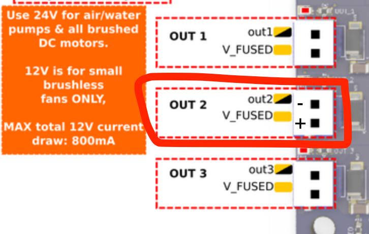
out3/4 should be powered ?

-
If it's a Duet 3 then OUT0+ is powered from the +VOUT0_IN input terminal, not from +VIN.
Duet WiFi hardware designer and firmware engineer
Please do not ask me for Duet support via PM or email, use the forum
http://www.escher3d.com, https://miscsolutions.wordpress.com -
@dc42
Yes it is a Duet3.
So I should power out_0 power in too from the PSU ? -
The SSR does not take a lot of current on its input, you can use a thin wire and one of the fan headers to simplify your wiring. Keeps your bed output free for things such switching LED lights...
-
@pixelpieper
Ok, thanks but not sure I understand .. -
@Touchthebitum I just had a look on the wiring diagram of the duet 3: you can configure your bed to use for example out 2 instead of the big screw terminals to control your SSR.
-
@pixelpieper
Ok, thanks -
@Touchthebitum Here is a sketch with the correct polarity for the SSR inputs:
You then have to adjust the configuration as follows:
M950 H0 C"out2" T0 ; create bed heater output on out0 and map it to sensor 0Voron V2.434 / Duet 3 Mini5+, Duet 3 Expansion Mini 2+, Duet 1LC V1.1 Toolboard
Voron V0.250 / Duet 2 Maestro -
@pixelpieper
Perfect")
Thanks -
@pixelpieper
Great it works like a charm. Thanks -
@Touchthebitum Nice!
-
@Touchthebitum said in Keenovo 220v setup:
@fcwilt
No, unfortunatelyYou're doing mains wiring without a multimeter?

I'm shocked, but hopefully you aren't!
-
@Phaedrux
No, I misunderstood the question, I mean I'm not very clever with it