@t3p3tony thanks, now it only has to become available at a European reseller ")
Best posts made by pixelpieper
-
RE: Announcement: Duet 3 Toolboard revision v1.1posted in Duet Hardware and wiring
-
RE: Configuring 12864 LCD on Maestro?posted in Duet Hardware and wiring
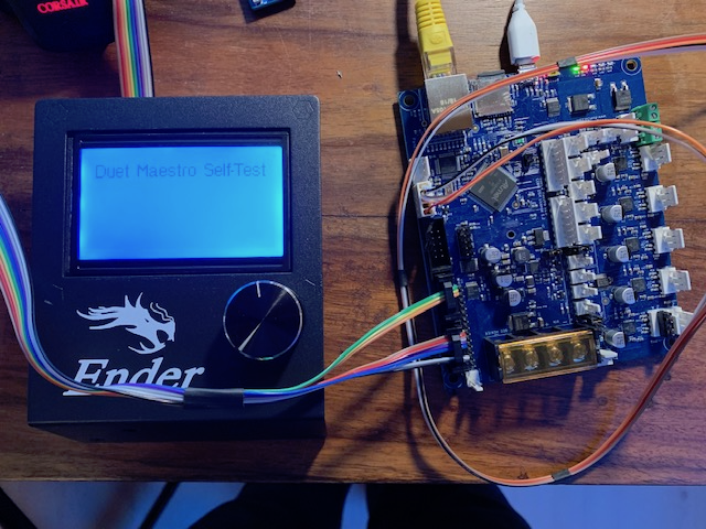
Hi, First post here, I thought that may help you guys out a bit...
If anyone else wants a simple clean way to create a single ribbon cable which does not involve dupont connectors: You can easily crimp yourself a cable, just get yourself some connectors (like this one, no affiliation with sparkfun). You can either reuse the existing cable or, simpler, get some rainbow ribbon cable which allows you to follow this color scheme:

All connectors as seen from the top, i.e. the order in which the pins are on the connectorsCrimp the cable on the LCD side with all wires, if using a rainbow ribbon align the marker (small triangle) with the brown wire so that the colors match up the illustration. Carefully cut the ribbon after two wires, in the center and finally just before the outer two wires. For the EXP1 connector align the first two and last two wires identical to their position on the LCD side. Take the second three wire pair and align it flipped over with the first wires. The top "bridge" of the connector has some indentations which helps with the proper alignment. You should have three remaining wires, these go into the exp2 connector, again flipped over. make sure to skip the first two positions and you should be fine.
Happy crimping!
--Edit--
Configuration when using this wiring to have the wheel inputs properly working:
M918 P1 E-4 -
RE: Non Duet Hardware with RRF ?posted in Duet Hardware and wiring
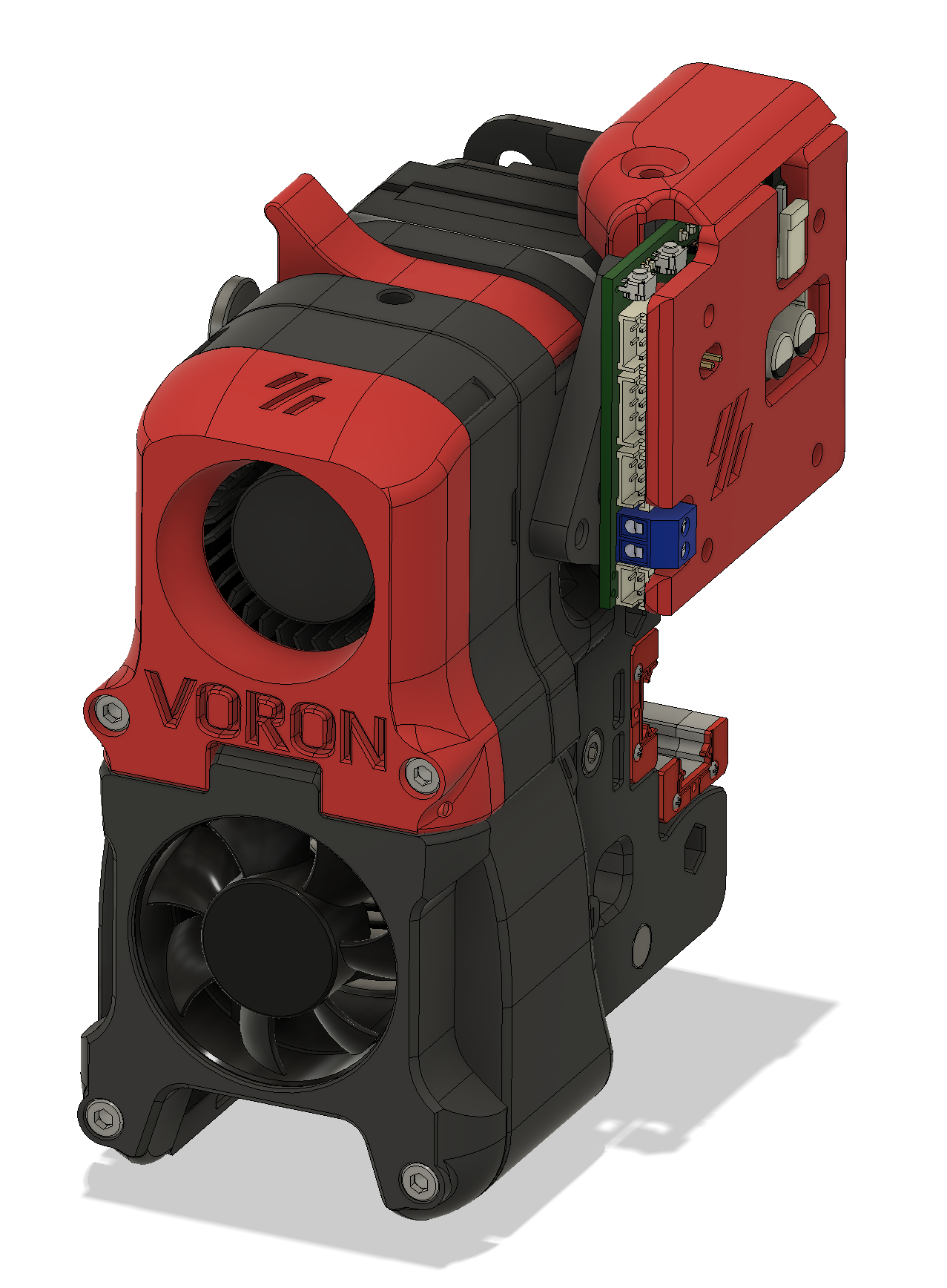
@Herve_Smith I have this experimental one which mounts the 1LC in the flap, leaves just enough room to allow for the chain and exposes the two buttons which I have programmed to extrude/retract


-
Neopixel support on 1LC?posted in Firmware wishlist
Would it be possible to add neopixel support to the 1LC firmware on IO0? I am aware that I will likely need to add a buffer as a level shifter and that I won’t be able to drive more than maybe three or four pixels, but it would simplify adding lights to the toolhead.
-
RE: RESOLVED. WAS: thermistor bug in 3.2beta 2 on Duet Maestroposted in Beta Firmware
Sorry for the confusion, it seems I might have had a wiring or crimp issue which by chance developed in parallel to playing with the beta. Having it seamingly disappear while downgrading did not help either...

I will replace all my hotend thermistors with PT1000, a wire fault resulting in to low a temperature reading is to dangerous in my opinion, so the upgraded sensors will give me some peace of mind.
-
RE: Heater Monitor Setup (M143)posted in Duet Hardware and wiring
Nevermind, Fixed it - Problem was the order of my commands, I now moved the M140 and M307 to before the M143 definition:
;; thermal ------------------------------------------------- ; Sensors -------------------------------------------------- M308 S0 P"bedtemp" Y"thermistor" T100000 B3950 A"Bedmat"; configure sensor 0 as thermistor on pin temp0 M308 S1 P"e0temp" Y"pt1000" A"Hotend" ; configure sensor 1 as thermistor M308 S2 P"ctemp" Y"thermistor" T100000 B3950 A"Chamber" ;Chamber fan M308 S3 Y"mcu-temp" A"Board" M308 S4 P"e1temp" Y"thermistor" T100000 B3950 A"Bedplate" ; Heaters -------------------------------------------------- ;Bed M950 H0 C"bedheat" T4 ; create bed heater output on out0 and map it to sensor 4 M950 H1 C"e0heat" T1 ; create nozzle heater output on e0heat and map it to sensor 1 M140 H0 ;PID Settings M307 H0 A301.0 C845.3 D1.4 S1.00 V23.6 B0 M307 H1 A482.6 C291.7 D5.5 S1.00 V23.6 B0 ;V6 ; Monitors & Limits M143 H0 P1 T0 A2 S110 C0 ; Regulate (A2) bed heater (H0) to have pad sensor (T0) below 110°C. Use Heater monitor 1 for it M143 H0 P2 T0 A0 S120 C0 ; Fault (A0) bed heater (H0) if pad sensor (T0) exceeds 120°C. Use Heater monitor 2 for it M143 H0 P0 S110 ; Set bed heater max temperature to 120°C, use implict monitor 0 which is implicitly configured for heater fault M143 H1 S400 ; set temperature limit for heater 1 to 275C -
RE: Comparing klipper and RRF input shaper data collectionposted in Beta Firmware
One thing I should have mentioned: these are two fundamentally different approaches to achieve the same thing.
-
Klipper does a sweep where they try to stimulate the system at different frequencies. The ideal input signal for this measurement is a perfect sinusoidal not containing other frequency components, the unknown factor here is how well the sinusoid is approximated by the acceleration/deceleration curves.
-
RRF measures an impulse response based on a fast movement. The ideal input signal here is a very fast acceleration which equally contains all the frequency components of interest. The question here is how well that is achieved.
Both should come to a similar conclusion.
-
-
Duet 2 Maestro and FYSETC Mini12864posted in Duet Hardware and wiring
After creating my third Maestro Mini12864 wiring loom I thought it might be time to create a Pinout for others to reuse...

This is for the Mini12864 in Version 1.2 without RGB - tested with RC1 of Version 3.2


-
RE: Comparing klipper and RRF input shaper data collectionposted in Beta Firmware
@gloomyandy said in Comparing klipper and RRF input shaper data collection:
Folks, please be aware that if you use this script with a the current version of RRF (V3.4beta6) or a previous version then you will only be able to collect a maximum of 64K samples (so approx 50 seconds of data, with a sample rate of approx 1320), given that the gcode generated by this script runs for longer than this you may not have good coverage of higher frequencies (as they come later in the test sequence). In my tests I am using a modified (and currently unreleased) version of RRF. Later versions of RRF may make it possible to collect more samples but that is up to @dc42. You may be able to experiment with a capturing the full range by setting your accelerometer to use a lower sampling rate, but this is not something I have tried.
It's been a while since I have had my signal processing classes, so feel free to correct any mistakes, but based on theory each acceleration and deceleration contain all the frequency components. (Ok, this is only true for an infinite acceleration / deceleration, but a fast move should be close enough to capture the frequency range of interest.)
The Klipper approach wiggling the head about is mainly giving you more data and hence a higher resolution of the spectrum which is why you see more noise in the plot.
Btw,. reducing the sampling rate "to capture the full range" will have the opposite effect: the Nyquist–Shannon sampling theorem applies and reducing the sampling rate reduces the maximum frequency that can be sampled which is f_sampling/2.
-
RE: Announcement: Duet 3 Toolboard revision v1.1posted in Duet Hardware and wiring
Any chance we can get a STEP for the new Version? I am trying to do a mount for a tight space, would be useful to have a complete 3d model. Guesstimates from the 1.0-Step wont work well as the connectors changed and the new board is slightly larger...
Latest posts made by pixelpieper
-
[Bug / Feature Request]: negative temperatures in chartposted in Duet Web Control wishlist
I am using a Duet board as a temperature controller for a measurement setup, using a peltier element for subzero temperatures. Unfortunately the temperature chart in DWC doesn't scale down to negative temperatures right now:
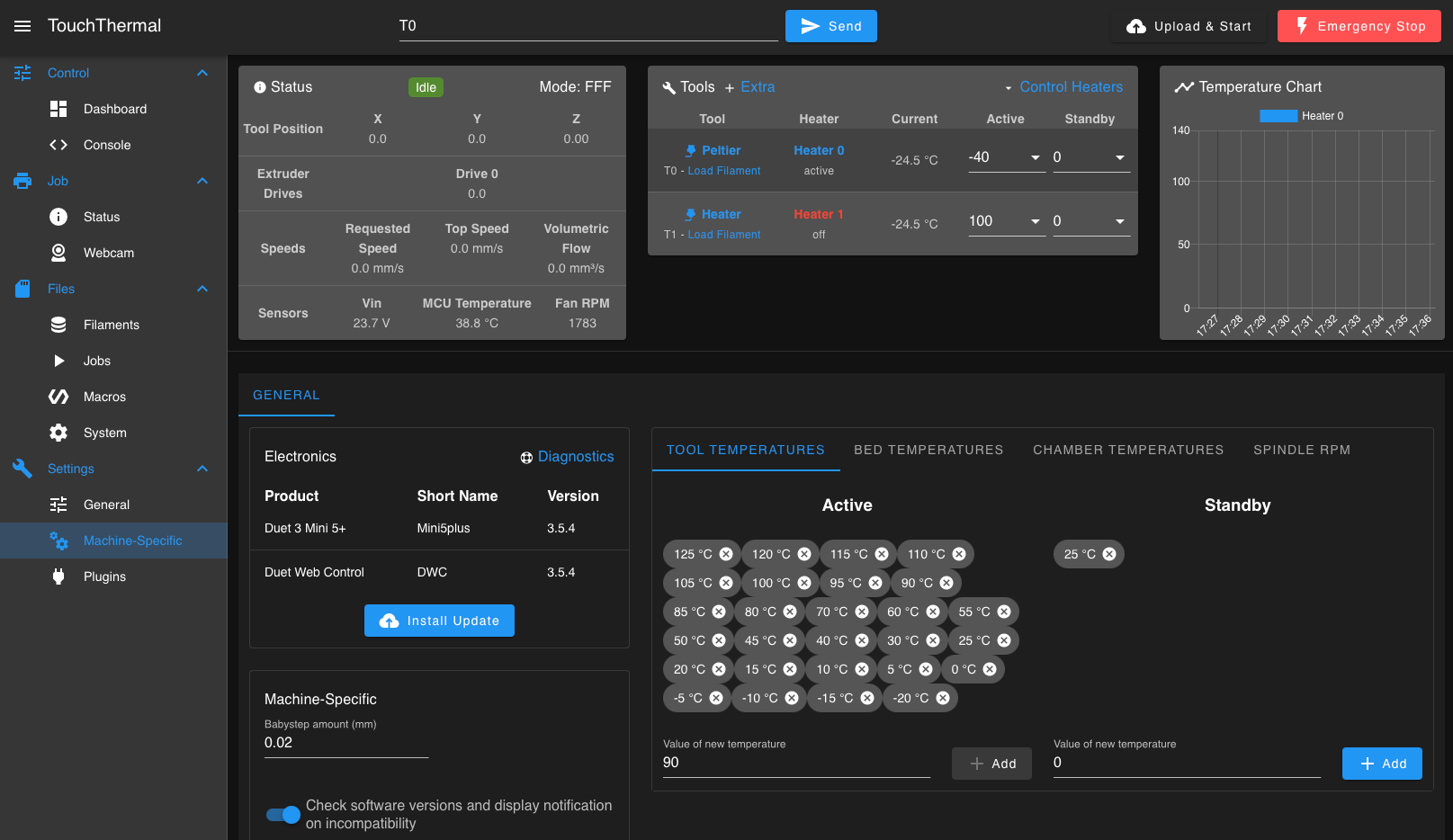
My proposal would be to extend the lowest temperature down to either
min(0, min(active_tooltemp_list),min(active_bedtemp_list),min(active_chambertemp_list))or
min(0, active_tool_temperature,active_bed_temperature, active_chamber_tamperature)This keeps the behavior as is for normal users while extending the chart down if required.
-
RE: Temperature fault at -4ºC / sensor for negative temperatures?posted in Duet Hardware and wiring
@dc42 Its a bit of a tradeoff, I want to cover a range from -20ºC to 120ºC, have to compare whether a 10k thermistor would still work well on the upper end - thanks for the suggestion!
-
RE: Temperature fault at -4ºC / sensor for negative temperatures?posted in Duet Hardware and wiring
In case anyone ever runs into this: I replaced the 2k2 series resistance on one of the thermistor inputs with a 10k resistor which shifted the range down to about -19ºC. Make sure to configure the 10k resistance in your config.g using the R parameter of M308. This will likely limit the measurement range on the upper end (which isn't a concern for my application).
M308 S0 P"ctemp" Y"thermistor" T100000 B3950 R10000 ; configure sensor 0 as thermistor on pin bedtemp -
Temperature fault at -4ºC / sensor for negative temperatures?posted in Duet Hardware and wiring
For a university test setup I am trying to control a peltier element with a duet 2 maestro board which seems to work quite well with enabling the inversion in M307.
Unfortunately, when I reach about -4ºC the thermistor stops working and the printed temperature jumps to -273.1ºC, triggering a heater fault event. Is this a firmware limit or can I work around by using a PT1000 / PT100 / K-Type Thermocouple instead?
Relevant config.g snippet:
M308 S0 P"bedtemp" Y"thermistor" T100000 B3950 ; configure sensor 0 as thermistor on pin bedtemp M950 H0 C"bedheat" T0 ; create nozzle heater output on bedheat and map it to sensor 0 M307 H0 B0 I1 S1.00 ; disable bang-bang mode for heater and set PWM limit -
RE: Support for RP2040?posted in Other control boards
@o_lampe it doesn't have dedicated CAN hardware, but it does have programmable GPIO (PIO) which can be used to implement CAN, offloading at least some of the processing into a sequencer like state machine. There is still a need for the processor to take care of some of the package handling, but since we have two cores it's not that bad...
-
RE: Erm, RRF 3.4.5 Announcement?posted in General Discussion
@dc42 Has there been any changes to the handling of relative/absolute movement? I did an update this morning and it broke my homing routine, driving the print head further even after triggering the endstop. Spend two hours trying to find a hardware gremlin - coincidentally there was a loose screw close to my hall sensor XY endstop board, so I had to remove the sensor board and had to disconnect the wiring, so that was my first suspect. Only after realizing that the endstops worked as expected in the object model I started suspecting a firmware issue and now tried to downgrade to 3.4.4 which fixed the problems.
Voron 2.4 with Duet 3 Mini 5+ / 1LC 1.1
For reference:
homeall.g working in 3.4.4, but failing in 3.4.5 (unessential stuff commented for debugging)
;; Slightly optimized XYZ home without performing extra z hops
var x_accel = move.axes[0].acceleration
var y_accel = move.axes[1].acceleration
var z_accel = move.axes[2].acceleration
var x_speed = move.axes[0].speed
var y_speed = move.axes[1].speed
var z_speed = move.axes[2].speed

M913 X50 Y50 Z50 ; half the currents
;M201 X{var.x_accel/2} Y{var.x_accel/2} Z{var.z_accel/4} ; quarter the accelerations
;M203 X{var.x_speed/2} Y{var.x_speed/2} Z{var.z_speed/4} ; quarter the speed

; relative movement
G91

; Lift Z relative to current position if needed

;if !move.axes[2].homed
;  G1 H2 Z5 F1800
;elif move.axes[2].userPosition < 10
;  G1 Z5 F9000

; Coarse home X or Y
;G1 X300 Y300 F2400 H1
;G1 X300 Y300 F2400 H1

; Coarse home X
G1 X600 H1

; Coarse home Y
G1 Y600 H1

; Move away from the endstops
;G1 X-50 Y-50 F9000

; Fine home X
;G1 X600 F360 H1

; Fine home Y
;G1 Y600 F360 H1

;M201 X{var.x_accel} Y{var.x_accel} ; reset the XY accelerations
;M203 X{var.x_speed} Y{var.x_speed} ; reset the XY speed

; Absolute positioning
G90                             ; absolute positioning

; Home Z with the switch at the back
;G1 X{global.z_stop_x} Y{global.z_stop_y} F99999             ; move to directly above mechanical Z-switch
;G30 K0 Z-9999 ; probe

G1 X{global.bed_center_x} Y{global.bed_center_y} F5000             ; move to center of bed
G30 K1 Z-9999 ; probe

; brush nozzle
M98 P"/macros/moveto/brush_xy.g"

G1 X{global.bed_center_x} Y{global.bed_center_y}  F5000             ; move to directly above mechanical Z-switch
G30 K1 Z-9999 ; probe again

; Restore high currents, speed & accel
M913 X100 Y100 Z100
M201 X{var.x_accel} Y{var.x_accel} Z{var.z_accel}
M203 X{var.x_speed} Y{var.x_speed} Z{var.z_speed}

; Move above center of the bed
G1 X125 Y125 Z50
config.g
;; system and network -------------------------------------- M550 PMunin ; hostname M669 K1 ; corexy mode M552 S1 P"M" M586 P2 S1 R23 T0 ; enable telnet M586 P1 S1 T0 ; enable ftp ;M555 P2 ; set Marlin output mode G21 ; millimeter units G90 ; absolute tool coordinates M83 ; relative extruder coordinates ; constants of the device geometry global max_x = 250 global max_y = 256 global z_stop_x = {global.max_x-24.5} global z_stop_y = {global.max_y-3} global bed_center_x = {global.max_x/2} global bed_center_y = {global.max_y/2} global mag_probe_x = 51 global mag_probe_y = {global.max_y} global mag_probe_z = 1.7 global QGL_probe = 3 ; 1 = inductive, 2 = magnet, 3 = tap ; speed & acceleration settings mm/min global xy_accel = 10000; global z_accel = 1000; global xy_speed = 60000; global z_speed = 6000; ;; enable paneldue ;M575 P1 B57600 S1 M569 P0 S1 ; E0 motor direction M569 P1 S0 ;D3 V5000 ; Y motor direction M569 P2 S1 ;D3 V5000 ; X motor direction M569 P5 S0 ; ZFL motor direction M569 P4 S1 ; ZBL motor direction M569 P3 S0 ; ZBR motor direction M569 P6 S1 ; ZFR motor direction M584 X2 Y1 Z5:4:3:6 E121.0 ; motor drive mapping M350 X16 Y16 Z16 E16 I1 ; set microstepping M92 X80 Y80 Z400 E727.5 ; set microsteps per mm ;;M574 X2 Y2 Z0 S1 ; endstops ;M574 Z1 S1 P"io4.in" ; Z min active high endstop switch M671 X-65:-65:315:315 Y-10:325:325:-10 S20 ; Z leadscrews positions M84 S3600 ; motor idle timeout M906 I50 ; motor idle current percentage ;E655 ; Mini 12864 M918 P2 E-4 R3 C100 ; Enable FYSetc Mini 12864 M150 X2 R255 U255 B255 S3 ; FYSETC Neopixel background: set all 3 LEDs to white ;M950 P0 C"io3.out" Q500 ; generate PWM pin (red on mini12864 V1.2) ;M42 P0 S0 ; turn off ;; geometry ------------------------------------------------ M208 X0 Y0 Z-3 S1 ; S1 = set axes minima M208 X{global.max_x} Y{global.max_y} Z235 S0 ; S0 = set axes maxima M208 X250 Y256 Z235 S0 ; S0 = set axes maxima M557 X20:240 Y25:235 S20 ; configure z probing grid for mesh compensation ;M98 P"/macros/zprobe/use_mfast.g" ;M98 P"/macros/zprobe/use_ifast.g" ; mechanical switch M558 K0 P5 C"io4.in" I0 H0 R0.1 F1200 T99999 A1 B1 G31 K0 X0 Y0 ; inductive probe ;M558 K1 P8 C"121.io2.in" I1 A3 H12 R0.1 F800 T99999 A1 B1 ;G31 P1000 K1 X0 Y25 Z0.318 ; magprobe ;M558 K2 P8 C"121.IO1.in" F150 T1000 H2 ;G31 P1000 K2 X-2.5 Y38.5 Z7 ; tap tap tappa di tap tap dooo M558 K1 P8 C"^121.io0.in" I1 A3 H12 R0.1 F800 T99999 A1 B1 G31 P1000 K1 X0 Y0 Z-0.76 ;; drive --------------------------------------------------- ;; Motor layout: ;; E0 E1 ;; YB XA ;; Z2 Z3 ;; Z0 Z1 ; Magnet homing M574 X2 S1 P"!io6.in" ; X min active low endstop switch M574 Y2 S1 P"!io5.in" ; Y min active low endstop switch ; Sensorless Homing ;M574 X2 S3 ;M574 Y2 S3 ;M915 X Y R0 F0 S3 ;; velocity, acceleration, and current settings are in these macros M98 P"/macros/drive/xy_fullcurrent.g" M98 P"/macros/drive/z_fullcurrent.g" M98 P"/macros/drive/e_fullcurrent.g" ;; firmware retraction ------------------------------------- ;; Choose one as your default: ;M98 P"/macros/retraction/quiet_nozhop.g ;M98 P"/macros/retraction/quiet_zhop.g M98 P"/macros/retraction/pa_nozhop.g" ;M98 P"/macros/retraction/pa_zhop.g" ;; thermal ------------------------------------------------- ; Sensors -------------------------------------------------- M308 S0 P"temp0" Y"thermistor" T100000 B3950 A"Bedmat"; configure sensor 0 as thermistor on pin temp0 M308 S1 P"121.temp0" Y"pt1000" A"Hotend" ; configure sensor 1 as thermistor ;M308 S1 P"e0temp" Y"thermistor" T100000 B3950 A"Hotend" M308 S2 P"121.temp1" Y"thermistor" T100000 B3950 A"Chamber" ;Chamber fan M308 S3 Y"mcu-temp" A"Board" ;M308 S4 P"e1temp" Y"thermistor" T100000 B3950 A"Bedplate" ; Heaters -------------------------------------------------- ;Bed M950 H0 C"out0" T0 ; create bed heater output on out0 and map it to sensor 4 M950 H1 C"121.out0" T1 ; create nozzle heater output on e0heat and map it to sensor 1 M140 H0 ;PID Settings M307 H0 A301.0 C845.3 D1.4 S1.00 V23.6 B0 M307 H1 A482.6 C291.7 D5.5 S1.00 V23.6 B0 ;V6 ; Monitors & Limits ;M143 H0 P1 T0 A2 S130 C0 ; Regulate (A2) bed heater (H0) to have pad sensor (T0) below 110°C. Use Heater monitor 1 for it ;M143 H0 P2 T0 A0 S135 C0 ; Fault (A0) bed heater (H0) if pad sensor (T0) exceeds 135°C. Use Heater monitor 2 for it M143 H0 P0 S130 ; Set bed heater max temperature to 120°C, use implict monitor 0 which is implicitly configured for heater fault M143 H1 S400 ; set temperature limit for heater 1 to 275C M912 P0 S-8 ;MCU tempurature sensor correction ;; fans ------------------------------------------------- ;Parts M950 F0 C"121.out2" Q500 M106 P0 S0 B0.1 L128 C"Part" ; part fan ;Hot End M950 F1 C"121.out1" Q500 M106 P1 T60 H1 C"Hotend" ; hotend fan PWMED DOWN ;Board cooling M950 F2 C"0.out3" Q500 M106 P2 S0.5 C"Board"; On when MCU temp (H3) reaches 45C ;H2 L180 X255 T30:50 ;M106 P2 S255 C"Board" M950 F3 C"0.out4" Q500 M106 P3 S0 C"Exhaust" M950 F4 C"0.out5" Q500 M106 P4 T40 H0 C"Nevermore" ;M950 F5 C"0.out1" Q500 ;M106 P5 S1 C"IKEAFILTER" ; Filter ;; tools --------------------------------------------------- M563 P0 D0 H1 ; bind tool 0 to drive and heater G10 P0 X0 Y0 Z0 ; tool offset G10 P0 S0 R0 ; tool active and standby temp T0 ; activate tool 0 ;; Accelerometer M955 P121.0 I05 ;; Input shaper M593 P"EI3" F41.6 S0.05 ;; filament sensor --------------------------------------- ;M591 D0 P3 C3 S0 R75:125 L24.8 E3.0 ; Duet3D rotating magnet sensor for extruder drive 0 is connected to E0 endstop input, enabled, sensitivity 24.8mm.rev, 85% to 115% tolerance, 3mm detection length ;M591 P5 C"e0stop" S1 ; Laser Filament Monitor ;; Buttons on the toolboard M950 C"121.button0" J0 M950 C"121.button1" J1 M581 P0 T2 M581 P1 T3 -
RE: Non Duet Hardware with RRF ?posted in Duet Hardware and wiring
@Herve_Smith I have this experimental one which mounts the 1LC in the flap, leaves just enough room to allow for the chain and exposes the two buttons which I have programmed to extrude/retract
-
RE: NEW Duet3D documentation site - now official!posted in Documentation
@droftarts Well done, this looks so much better than the Dozuki, must have been a ton of work.
-
RE: Low effort Duet controlled air filter: IKEA Förnuftigposted in General Discussion
@jay_s_uk here you go. Note that the VOC activated carbon filter is sold separately.