Triple Z motors not correcting
-
@nriviera said in Triple Z motors not correcting:
Annoyingly you can't make each Z axis move independent of the other to test that they are correct in the config.
You can if you temporarily bind each Z motor driver to its own axis. Then you can move them independently manually. Just be careful not to rip your bed apart.
@mrenz999 said in Triple Z motors not correcting:
Current configuration is 0,0 far left.
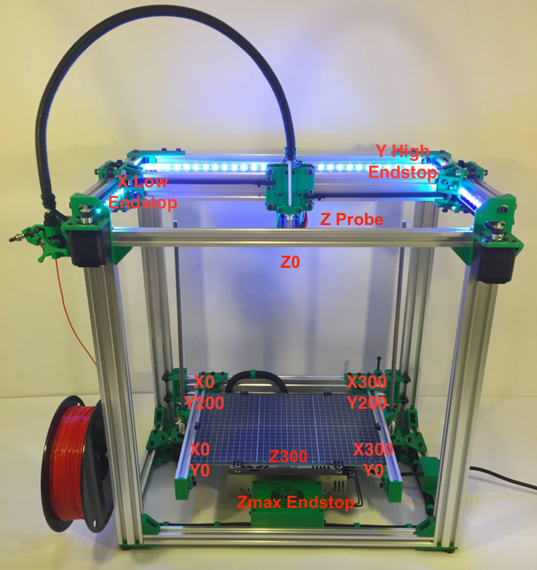
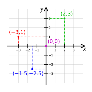
Far left as in rear left? That may be a bit of a problem as you're not using a right handed coordinate system. 0,0 should be in the front left, +X to the right, -X to the left, -Y to the front, +Y to the back.
Regardless, this is the key part of the configuration that you're missing
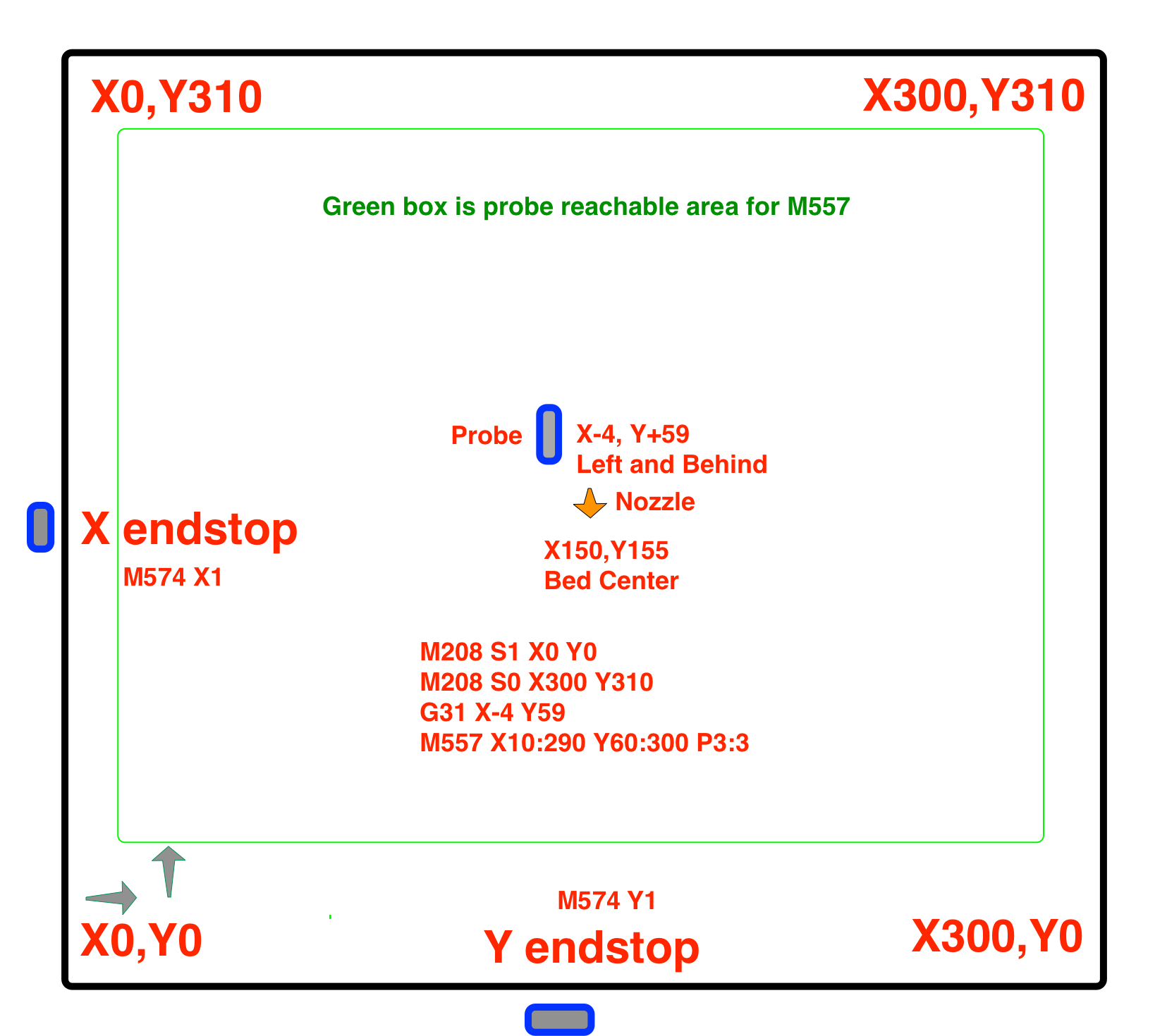
You must use the M671 command to define the X and Y coordinates of the leadscrews. The M671 command must come after the M584 command and must specify the same number of X and Y coordinates as the number of motors assigned to the Z axis in the M584 command; and these coordinates must be in the same order as the driver numbers of the associated motors in the M584 command. The M671 command must also come after any M667 or M669 command.
https://duet3d.dozuki.com/Wiki/Bed_levelling_using_multiple_independent_Z_motors
-
@Phaedrux A right handed system ? My endstops are Y to the far rear and x to the left. Therefore, Y + is towards the front and X+ is to the right.
-
With Y flipped like that you're likely to get mirrored prints.
Your Y axis endstop is at the high end of travel in that case and when triggered would set the coordinate position to the M208 Y maxima, rather than 0.
-
@Phaedrux As my endstops are to the rear and left what should I change to make that flip without changing where the endstops are ?
-
Post your config.g and homeall.g
M574 Y2 and in homeall the direction of the Y homing move would be positive instead of negative.
If this is corexy you'll also need to do some tests to verify your motor connections and rotation directions are correct.
https://duet3d.dozuki.com/Wiki/ConfiguringRepRapFirmwareCoreXYPrinter#Section_Testing_motor_movement
-
; generated by RepRapFirmware Configuration Tool v3.1.1 on Thu Jun 04 2020 11:20:25 GMT-0700 (Pacific Daylight Time)
G91 ; relative positioning
G1 H2 Z5 F6000 ; lift Z relative to current position
G1 H1 X-450 Y-450 F1800 ; move quickly to X and Y axis endstops and stop there (first pass)
G1 H1 X-450
G1 H1 Y-450
G1 X5 Y5 F6000 ; go back a few mm
G1 H1 X-450 Y-450 F360 ; move slowly to X and Y axis endstops once more (second pass)
G1 X264 Y250 F9000 ; go to first bed probe point and home Z
G30 ; probe the bed
; Configuration file for Duet 3 (firmware version 3)
; executed by the firmware on start-up
;
; generated by RepRapFirmware Configuration Tool v3.1.3 on Tue Jun 16 2020 08:02:01 GMT-0700 (Pacific Daylight Time); General preferences
G90 ; send absolute coordinates...
M83 ; ...but relative extruder moves
G21 ; Set units to MM
M550 P"Duet 3" ; set printer name
M669 K1 ; select CoreXY mode;Network
M552 S1 ; enable network
M586 P0 S1 ; enable HTTP
M586 P1 S0 ; disable FTP
M586 P2 S0 ; disable Telnet; Drives
M569 P0.0 S0 ; physical drive 0.0 goes forwards
M569 P0.1 S1 ; physical drive 0.1 goes backwards
M569 P0.2 S0 ; physical drive 0.2 goes forwards
M569 P0.3 S0 ; physical drive 0.3 goes forwards
M569 P0.4 S1 ; physical drive 0.4 goes backwards
M569 P0.5 S0 ; physical drive 0.3 goes forwards
M584 X0.0 Y0.1 Z0.2:3:4 E0.5 ; set drive mapping
M350 X16 Y16 Z16 E16 I1 ; configure microstepping with interpolation
M92 X80.00 Y80.00 Z400.00 E405.18 ; set steps per mm
M566 X600.00 Y600.00 Z24.00 E300.00 ; set maximum instantaneous speed changes (mm/min)
M203 X20000 Y20000 Z600 E2000.00 ; set maximum speeds (mm/min)
M201 X3000.00 Y3000.00 Z600.00 E5000.00 ; set accelerations (mm/s^2)
M906 X1600 Y1600 Z1600 E1600 I30 ; set motor currents (mA) and motor idle factor in per cent
M84 S30 ; Set idle timeout
M671 X20:20:430 Y110:365:240 S9 ; leadscrews at rear left, front middle and rear right; Axis Limits
M208 X-20 Y-15 Z0 S1 ; set axis minima
M208 X500 Y500 Z465 S0 ; set axis maxima; Endstops
M574 X1 S1 P"!io0.in" ; configure active-high endstop for low end on X via pin !io0.in
M574 Y1 S1 P"!io1.in" ; configure active-high endstop for low end on Y via pin !io1.in
M574 Z1 S2 ; configure Z-probe endstop for low end on Z; Z-Probe
;M950 S0 C"io7.out" ; create servo pin 0 for BLTouch
;M558 P9 C"^io7.in" H5 F120 T6000 ; set Z probe type to bltouch and the dive height + speeds height + speeds
;G31 P500 X-40 Y-10 Z6 ; set Z probe trigger value, offset and trigger height
M557 X20:430 Y15:410 S20 ; define mesh grid
Z-Probe
M558 P8 C"^io7.out"
G31 P500 X-20 Y-15 Z2; Heaters
M308 S0 P"temp0" Y"thermistor" T100000 B4008 ; configure sensor 0 as thermistor on pin temp0
M950 H0 C"out0" T0 ; create bed heater output on out0 and map it to sensor 0
M307 H0 B0 S1.00 ; disable bang-bang mode for the bed heater and set PWM limit
M140 H0 ; map heated bed to heater 0
M143 H0 S120 ; set temperature limit for heater 0 to 120C
M308 S1 P"temp1" Y"thermistor" T100000 B3950 ; configure sensor 1 as thermistor on pin temp1
M950 H1 C"out1" T1 ; create nozzle heater output on out1 and map it to sensor 1
M307 H1 B0 S1.00 ; disable bang-bang mode for heater and set PWM limit
M143 H1 S300
M307 H0 A188.5 C683.1 D0.2 S1.0 V24.1 B0
M307 H1 A351.2 C120.5 D7.2 S1.0 V24.1 B0; Fans
M950 F0 C"out7" Q500 ; create fan 0 on pin out7 and set its frequency
M106 P0 S1 H-1 ; set fan 0 value. Thermostatic control is turned off
M950 F1 C"out8" Q500 ; create fan 1 on pin out8 and set its frequency
M106 P1 S1 H-1 ; set fan 1 value. Thermostatic control is turned off
M950 F2 C"out9" Q500 ; create fan 2 on pin out9 and set its frequency
M106 P2 S1 H-1 ; set fan 2 value. Thermostatic control is turned off; Tools
M563 P0 D0 H1 F0 ; define tool 0
G10 P0 X0 Y0 Z0 ; set tool 0 axis offsets
G10 P0 R0 S0 ; set initial tool 0 active and standby temperatures to 0C; Custom settings are not defined
; Miscellaneous
T0
M575 P1 S1 B57600 ; enable support for PanelDue
M911 S10 R11 P"M913 X0 Y0 G91 M83 G1 Z3 E-5 F1000" ; set voltage thresholds and actions to run on power loss
M501 -
@mrenz999 said in Triple Z motors not correcting:
M671 X20:20:430 Y110:365:240 S9 ; leadscrews at rear left, front middle and rear right
are you sure thats correct? this would mean the leadscrews are inside the bed.
-
@Veti It's the probe spot. On the bed where it can probe closest to the leadscrew.
-
@mrenz999 said in Triple Z motors not correcting:
G1 H1 X-450 Y-450 F1800 ; move quickly to X and Y axis endstops and stop there (first pass)
G1 H1 X-450
G1 H1 Y-450
G1 X5 Y5 F6000 ; go back a few mm
G1 H1 X-450 Y-450 F360 ; move slowly to X and Y axis endstops once more (second pass)
G1 X264 Y250 F9000 ; go to first bed probe point and home Z
G30 ; probe the bedIn your homeall switch the direction of all the Y moves as shown here. Also the move to position the probe should probably be defined in absolute coordinates.
G1 H1 X-450 Y450 F1800 ; move quickly to X and Y axis endstops and stop there (first pass)
G1 H1 X-450
G1 H1 Y450
G1 X5 Y-5 F6000 ; go back a few mm
G1 H1 X-450 Y450 F360 ; move slowly to X and Y axis endstops once more (second pass)
G90 ; absolute position
G1 X264 Y250 F9000 ; go to first bed probe point and home Z
G30 ; probe the bed
Then in config.g you'd need to change the M574 for the Y axis to tell it the endstop is at the high end. That's Y2 instead of Y1
M574 Y2 S1 P"!io1.in" ; configure active-high endstop for low end on Y via pin !io1.inM584 X0.0 Y0.1 Z0.2:3:4 E0.5 ; set drive mapping M671 X20:20:430 Y110:365:240 S9 ; leadscrews at rear left, front middle and rear rightThe order and position of the lead screws will need to change, first to match the order of the motors defined in M584 but also the coordinates will be different now that your Y axis is flipped.
And as Veti says, try to estimate where the lead screws are actually positioned in absolute space relative to the 0,0 position in the front left corner even if they are outside the reachable area. It's only the points defined in the bed.g that need to be within the reachable area.
Which leads us to the bed.g points. You'll need to amend those as well now that the Y axis is flipped.
Also, don't forget to do those motor movement tests for corexy I linked.
Oh and your Z probe offset will need to be redone to reflect the new Y axis direction.
Oh and you might want to edit homey.g as well to change the directions of the homing moves.
-
@mrenz999 said in Triple Z motors not correcting:
It's the probe spot. On the bed where it can probe closest to the leadscrew.
those go in the bed.g not the M671 command.
the M671 are the actual positions of the leadscrew.