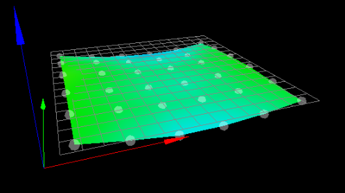
problem with irregular bltouch mesh
-
@Phaedrux I inserted it in my home z, it seems that everything works fine
; homez.g ; called to home the Z axis ; ; generated by RepRapFirmware Configuration Tool v3.1.1 on Fri Jun 05 2020 16:15:12 GMT-0300 (Horário Padrão de Brasília) G91 ; relative positioning G1 H1 Z-350 F900 ; move Z down until the endstop is triggered G90; G1 X150 Y150 Z3 F6000; raise for clearance G30 ; probe the bed M671 X-43:343 Y165:165 S1; parafusos de avanço à esquerda (conectado a Z) e à direita (conectado a E1) do eixo X M208 X0:300 Y0:300; G30 P0 X10 Y150 Z-99999; sonda perto de um parafuso de avanço, a meio caminho ao longo do eixo Y G30 P1 X290 Y150 Z-99999 S2; sonda perto de um parafuso de avanço e calibre 2 motores G1 X5 Y5 F6000; -
@RODOKAS said in problem with irregular bltouch mesh:
M671 X-43:343 Y165:165 S1; parafusos de avanço à esquerda (conectado a Z) e à direita (conectado a E1) do eixo X M208 X0:300 Y0:300;
That part should go in the config.g
You should also add an additional G30 at the center of the bed after the tilt correction since changing the tilt will change the Z0 point as well.
-
@Phaedrux thank you very much for the help, my g codes are cleaner and more correct, however I carried out new tests and saw no difference, I believe that some problem is not in firmware, to eliminate the possibility of a problem with the screws, I put it on the slicer for the jump za each travel movement in about 4 mm, thus eliminating any possibility of clearance on the z axis, even so I did not have any different results, the right side of the printer, where I have y + is always higher and I cannot make the engines compensate for that. the mesh is good but in practice that side gets higher.
this is the current mesh, everything looks perfect, but when I print I don't get the same in practice as the theory, it seems that the motors do not obey the correct values of the mesh.

-
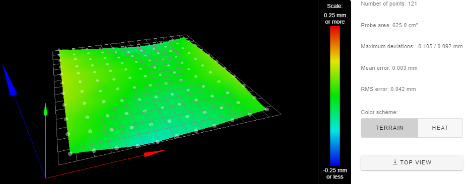
I also tried a mesh with more stitches, 121, but I got the same result, the right side of the machine, the first layer is more crushed, the only way to correct this is by using the table screws after creating the mesh.

-
When you run the leveling probes what results do you get in the console?
G30 P0 X10 Y150 Z-99999; sonda perto de um parafuso de avanço, a meio caminho ao longo do eixo Y
G30 P1 X290 Y150 Z-99999 S2; sonda perto de um parafuso de avanço e calibre 2 motoresYou may need to run the leveling passes more than once.
-
@Phaedrux
G28:
Leadscrew adjustments made: 0.105 0.104, points used 2, (mean, deviation) before (0.104, 0.001) after (0.000, 0.000)G29:
121 points probed, min error -0.105, max error 0.092, mean 0.003, deviation 0.042 -
@Phaedrux said in problem with irregular bltouch mesh:
G30 P0 X10 Y150 Z-99999; sonda perto de um parafuso de avanço, a meio caminho ao longo do eixo Y
G30 P1 X290 Y150 Z-99999 S2; sonda perto de um parafuso de avanço e calibre 2 motoresCopy and paste that section a few times to run it multiple times in a row.
@RODOKAS said in problem with irregular bltouch mesh:
the right side of the printer, where I have y + is always higher and I cannot make the engines compensate for that. the mesh is good but in practice that side gets higher.
Just to confirm that we're dealing with a standard coordinate system, 0,0 is the front left corner and +x goes to the right, -X to the left, +y to the back, and -Y to the front.
-
@RODOKAS said in problem with irregular bltouch mesh:
I also tried a mesh with more stitches, 121, but I got the same result, the right side of the machine, the first layer is more crushed, the only way to correct this is by using the table screws after creating the mesh.
Are you sure that mesh compensation is active during printing?
Do you perhaps have a stray G32 somewhere. The only bed.g code I see cancels mesh compensation.
Frederick
-
yes
-
@fcwilt there is no lost g32, but now i have fixed my beg.g file so as not to cancel the leveling anymore.
-
the result was wrong when the mesh compensation was active, as the table was not with uneven corners, I decided to try without the bed leveling active because at home it does the leveling of the sides of the table by the motors, so in theory even without active mesh was not to have differences close to the spindles.
resultaldo, the same error. so even when leveling the spindles using the bltouch, which is very good, and disabling the mesh compensation, in the first layer there is a difference between the points near the spindles, this could not exist because the spindles were leveled using the bltouch. I am really confused on what could be happening because I discard mesh error, firmware.
thank you all for trying. -
There are other reasons for the mesh to not match the bed. Since we're only leveling two motors, it's only tilt correction. You need 3 points to create a plane. Even then the bed itself can be warped in some way. Not only that, there is the X and Y travel ways which can be warped or not square/parallel/true. There can also be tilt of the print head which varies between XY coordinates which causes inaccurate measurements.
The function does work on other printers, so you'll need to find out what is different about your printer that is preventing it from working properly.
-
@Phaedrux
Thank you! -
Not sure if this was covered here. Do you perform the bed mesh with the bed at printing temperature?
-
@zapta yes
-
@Phaedrux
you were right, after the home all and the two engines are aligned with the table, I decided to make a g30 on each side (x5 and x295) and try to lower the nozzle to the table to see if there is a difference.
the result: at x5 and in the center of the table, the g30 corresponds exactly, so after the g30, I put the nozzle at 0.1 and it really has 0.1. But in position x295 after g30, I should have the same result, but immediately after g30, when I send the nozzle go up to 0 it touches the table, and I found that it only moves away from the table when it is at 0.2, so I have that difference.
There is no software error, there is no mesh error. all measurements were made at 150 y.
as much as I insist on the g30 in position x295 and y150 I have the same result, it is as if the bltouch measured wrong only in that position, the whole mechanics seems to be correct, but I do not understand what may be happening. -
Good construction


-
Hi,
Attached is a 4 point height map of my FT5 printer which is currently undergoing some upgrades.
While it might look like the problem is in the bed it is actually in the left and right Y rails.
Instead of the two rails being in the same plane, the right rail is canted with respect to the plane of the left rail.
When I get around to fixing this problem I will need to lower the rear end and raise the front end of the this rail.
As was mentioned by @Phaedrux there are a few different things that can contribute to a less than perfect height map - this rail problem is just one of them.

-
@fcwilt thanks for the example. but in my case the touch does not understand the bed slightly higher at x +, it is as if on the right side of the table the z offset was different from the left side of the table. I need to identify where there may be a difference for this to happen, when I find it I will put it here. thank you