Confused on wiring for Ender 3 Pro Conversion
-
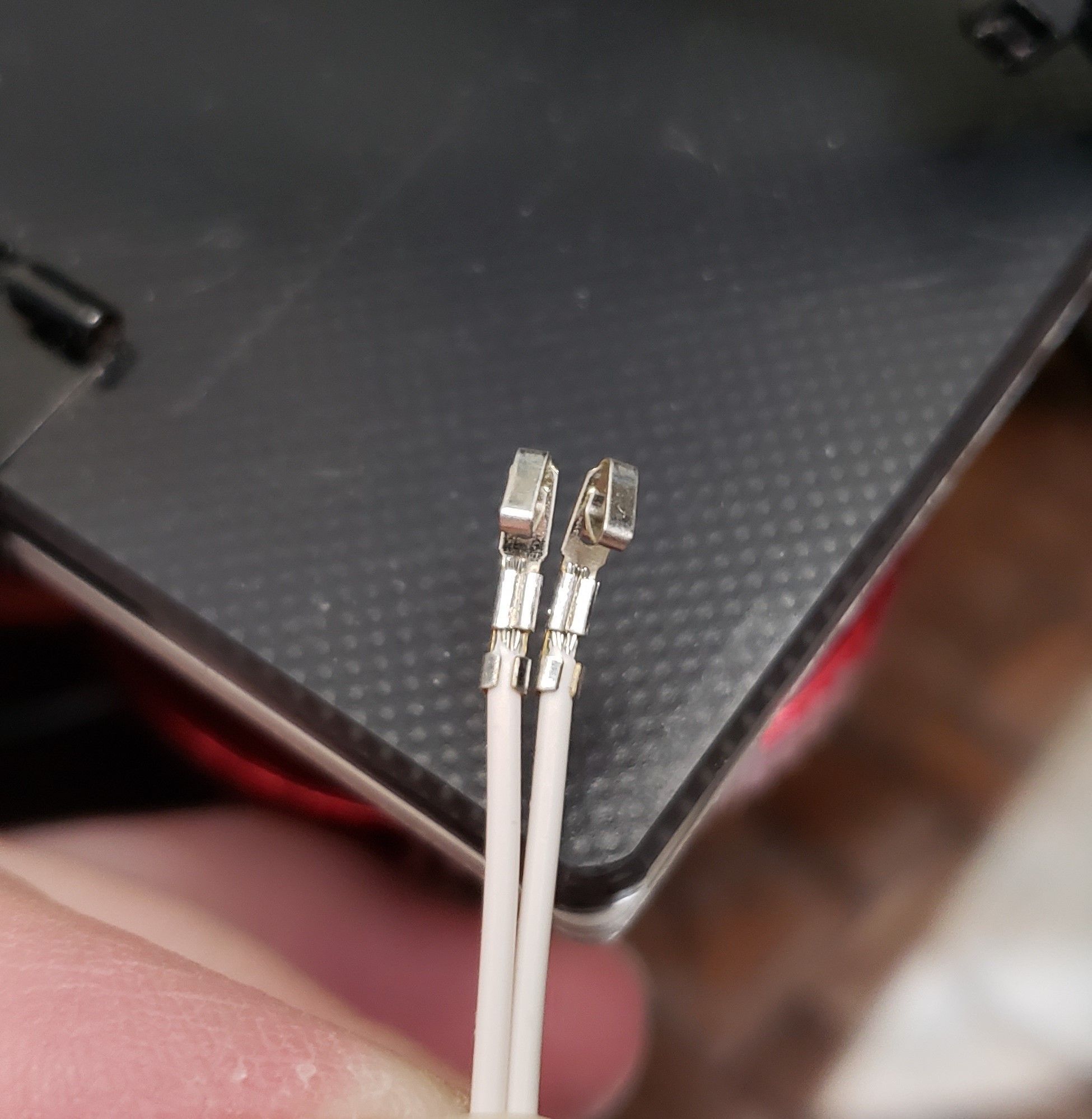
It's showing open circuit on both your heaters. Are the wires actually connected? Bad crimp?
-
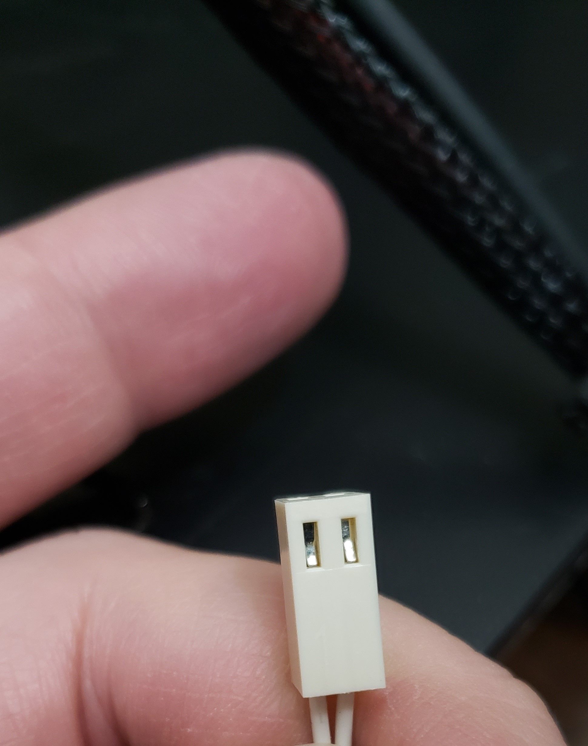
Not my best but not my worst. Pins are seated properly too.
-
Just to verify
-
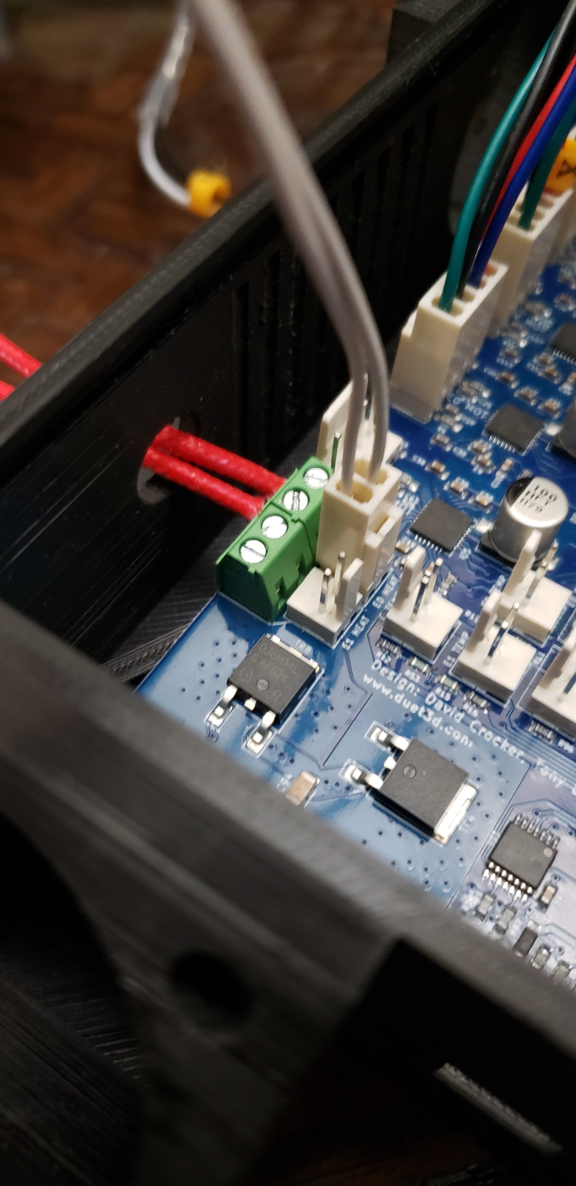
Last picture show the thermistor connected in parallel with the heater element.
The two pin header labeled E0 Temp is probably the one you wanted to use. It would help to measure the resistance across the two wires coming from the thermistor if it doesn't work on the correct input to see if the sensor/wiring is okay or not. I guess if subjected to Vin for some time it might not survive due to the heat generated as the resistance drops with increasing temperature.
-
@bearer Further up you'll see that it was mentioned for me to move the Therm to this connector. I did originally have it connected to E0 TEMP.
-
Maybe I fixed the photo cause I had made the same mistake originally. Will look closer tomorrow after sleep.
-
If you have a multimeter try to measure the resistance of the sensor to see if its wired correctly. Disconnect the plug and measure on the crimps in the plug, with thin enough probes you don't even have to remove the crimps from the plug. You should most likely measure around 100k ohm at room temp (20C).
-
@Phaedrux Well, just now moved it to that other set I originally had it on and still the same thing.
-
@Destruct0Dan said in Confused on wiring for Ender 3 Pro Conversion:
M308 S0 P"bedtemp" Y"thermistor" T9880 B4185 ; configure sensor 0 as thermistor on pin bedtemp
M308 S1 P"e0temp" Y"thermistor" T9880 B4185 ; configure sensor 1 as thermistor on pin e0tempyou mistyped your resistance value its 98801
-
@Veti Ah thank you. I take it I need to go through the configurator again to fix that?
-
no on the duet web ui you can edit the file directly. go to system and click on config.g
-
@Veti added the 1 to both lines that was missing it. Restarted and now to see what it says. Thank you for pointing that out. I had gone through that process a couple times and thought I entered the one like needed. Guess not.
Now my temps are reading the way they should. Now just continue through the setup process from the config setup portion? Also, does it mention where or how to adjust for using a TH3D EZABL Pro for my Z axis?
-
@Destruct0Dan said in Confused on wiring for Ender 3 Pro Conversion:
Also, does it mention where or how to adjust for using a TH3D EZABL Pro for my Z axis?
according to this
https://forum.duet3d.com/topic/4671/rewire-ezabl-capacitive-npn-z-probe-kit-for-duet
its a npn sensorfor wiring see
-
@Veti I'll read over those. Thank you.
Now I am also getting this when testing the bed. Seems it's warming up pretty slow. 1 degree in about 6-8 seconds.

-
you have to pid tune your bed and heater.
https://duet3d.dozuki.com/Wiki/Tuning_the_heater_temperature_control
-
@Veti oof. Talk about crash coursing in 3dPrinting. lol
Now about the sensor, I already have the TH3D control box that replaces the switch itself and just plugs into the Z stop position on the controller. Is it advised to not do that anymore and just connect only by what's mentioned in what you linked?
-
@Destruct0Dan said in Confused on wiring for Ender 3 Pro Conversion:
I already have the TH3D control box that replaces the switch itself and just plugs into the Z stop position on the controller. Is it advised to not do that anymore and just connect only by what's mentioned in what you linked?
i dont have an EZABL probe. what i believe the controll box does, is allow the 12v or 24v power required for the sensor to be used and connect them to a normal endstop because overwise they would fry the board.
the duet maestro endstop pin in 30V tolerant, so the sensor can be connected directly.
however you could also just connect the controller box, that should also work. -
@Veti So I am noticing that my HotEnd is listed as Heater 1. Should I switch my cables over to 1 instead of 0?
-
no that is correct
see your config
M950 H1 C"e0heat" T1 ; create nozzle heater output on e0heat and map it to sensor 1
-
So I went back through my photos from the guide and I had originally had the thermistor connected to the wrong port. The photo is still there actually (it's used to show the stepper motor connections). The thermistor connection section does show the correct position though.
Sorry I confused myself there. and Glad Veti got you sorted on the heater fault.