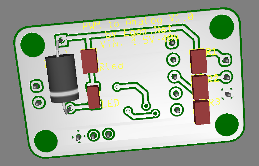
Designing a PWM to Analog mini board for fans
-
@taconite said in Designing a PWM to Analog mini board for fans:
So to just get it straight the PCB is converting a PWM Voltage (5V, 12V, 24V which ever you like) with duty cycle from 0% to 100% to a "real" analog voltage (which ever you like because it is decoupled) from 0 V to around Vin, right?
Do you supply the files with Assembly? If you order and ship to Germany I would take a hand full

What timeline are you looking for?
You got it right! The only limitation is that PWM voltage (in case is not a open drain like Duets) must be equal or lower than VCC (so you can use a 5V PWM to output an analog range from 0 to 24V, but you can't use a 24V PWM to output an analog range from 0 to 5V)
And keep in mind current consumption. At 50% PWM, the transistor will be wasting (half voltage)x(half current) watts, so you'd need quite a hefty heatsink for moderate currents, or even a bigger transistor. The planned BD139 should be good up to 3W well heatsinked.
Keep also in mind that fan voltage is not referenced to GND, but to VCC.
Regarding supply, I can send you the DIY kit (board+components), or assembled and tested board. Also can send the gerbers and BOM so you can do it all by yourself.
I'm ordering the PCB's this very weekend, so it should be about 20 days or so to be testing the first batch.
-
@Egon-Net
mhh thats a bummer . I wanted to do 12V PWM to 5 V analog.
But as it seems you are a specialist in electronics. Do you have an idea why this simple optocoupler didn't work for that purpose:
https://forum.duet3d.com/topic/19325/powering-arduino-nano-and-leds-from-5v-rail/12Custom ANET A8
Custom Delta: D-PATCH (Delta Printer with Automatic Tool CHanging) https://forum.duet3d.com/topic/16082/d-patch?_=1596131234754All I do here is under this license: CC BY-NC-SA
-
@Egon-Net said in Designing a PWM to Analog mini board for fans:
Comments?
Looks great and cute
")
A few random thoughts, please take with a grain of salt.
-
Are the components at the back of the board optional?
-
It seems that the new layout considerably restricted the ground path from the GND input to the transistor. I don't know if it matters or not.
-
Is there sufficient clearance for a spacer wall at the bottom, at the screw hole near the diode? Hard to see from the pictures here.
-
You may want to add voltage input specification on the top of bottom silk screen. e.g. 12V - 24V or whatever the range is.
-
I think that VCC typically means +5V. Maybe change to Vin+
-
The PWM input is active low. That is, if ones measure 10% high, it means 90% PWM value. I wonder if it can be conveyed somehow on the board to avoid confusion.
Looking at the responses here, it seems to be a great ideas that will benefit many.
-
-
@taconite said in Designing a PWM to Analog mini board for fans:
@Egon-Net
mhh thats a bummer . I wanted to do 12V PWM to 5 V analog.But as it seems you are a specialist in electronics. Do you have an idea why this simple optocoupler didn't work for that purpose:
https://forum.duet3d.com/topic/19325/powering-arduino-nano-and-leds-from-5v-rail/12Do you realize you could just use the PWM- from duet and 5V instead of Duet's Fan Vcc? You are not forced to use 24V/12V from Duet.
Here you have a example just with passive components:
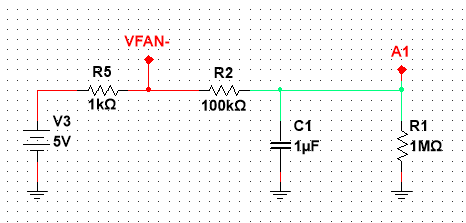
Since your load is Arduino's analog input, and assuming it has quite a high input impendance (IIRC, 1MOhm) you could just pull-up with your 5V supply with a 1K resistor (5mA current draw) and use VFan- from Duet (which is a PWM open drain). You'll have a little offset from de resistive divisor around A1, but it would be small. According my simulations, 2.3V for 50% PWM, 0V for 0% PWM and 4.54V por 100% PWM. You can play with R2 and C1 values a bit more to achieve even better results (for example 10k-10u).
Of course you could also use my board, but I think your problem doesn't need it.
-
@zapta said in Designing a PWM to Analog mini board for fans:
@Egon-Net said in Designing a PWM to Analog mini board for fans:
Comments?
Looks great and cute
A few random thoughts, please take with a grain of salt.
- Are the components at the back of the board optional?
No, just the led and its resistor are optional
- It seems that the new layout considerably restricted the ground path from the GND input to the transistor. I don't know if it matters or not.
There's a dual GND plane, top and bottom are GND. Plenty of copper for GND
")
- Is there sufficient clearance for a spacer wall at the bottom, at the screw hole near the diode? Hard to see from the pictures here.
A real diode is not as huge as in the render, so there should be no problem. Just in case, I was going to print the PCB in paper and check the clearances for every hole. We could also use a SMD diode, but I have a lot of 1N4001 at home, that's why I picked it.
- You may want to add voltage input specification on the top of bottom silk screen. e.g. 12V - 24V or whatever the range is.
Good idea. It should be good for 4.5V-40V (But the hight the voltage, the lower the usable current due to power dissipation)
- I think that VCC typically means +5V. Maybe change to Vin+
Mmm VCC for me means "any positive voltage", but I can rename it to Vin+ if it seems clearer.
- The PWM input is active low. That is, if ones measure 10% high, it means 90% PWM value. I wonder if it can be conveyed somehow on the board to avoid confusion.
PWM is active low, but I configured the comparator opamp to do inversion, so it follows the PWM percentage. It will be active low when using PWM voltage.
Looking at the responses here, it seems to be a great ideas that will benefit many.
I'm very glad!
-
@taconite said in Designing a PWM to Analog mini board for fans:
But as it seems you are a specialist in electronics. Do you have an idea why this simple optocoupler didn't work for that purpose:
https://forum.duet3d.com/topic/19325/powering-arduino-nano-and-leds-from-5v-rail/12What exactly do you want to achieve? An Arduino reading the FAN PWM output from a duet?
The optocoupler provides electrical isolation which you may or may not need. Then you can convert it to analog signal as feed it to the Arduino as such (see @Egon-Net's explanation) or feed it to the Arduino as a digital signal and let the Arduino determine the PWM value (e.g. using this standard function https://www.arduino.cc/reference/en/language/functions/advanced-io/pulsein/ ).
-
@zapta said in Designing a PWM to Analog mini board for fans:
@taconite said in Designing a PWM to Analog mini board for fans:
But as it seems you are a specialist in electronics. Do you have an idea why this simple optocoupler didn't work for that purpose:
https://forum.duet3d.com/topic/19325/powering-arduino-nano-and-leds-from-5v-rail/12What exactly do you want to achieve? An Arduino reading the FAN PWM output from a duet?
The optocoupler provides electrical isolation which you may or may not need. Then you can convert it to analog signal as feed it to the Arduino as such (see @Egon-Net's explanation) or feed it to the Arduino as a digital signal and let the Arduino determine the PWM value (e.g. using this standard function https://www.arduino.cc/reference/en/language/functions/advanced-io/pulsein/ ).
Didn't know about pulsein function, but for me it seems the way to go...
-
haven't heard about the pulsein function aswell. I wanted to get the 24V (or 12V) PWM into an equivalent 5V analog voltage hence the optocoupler. But principle should work, shouldn't it?
EDIT:
@Egon-Net said in Designing a PWM to Analog mini board for fans:@taconite said in Designing a PWM to Analog mini board for fans:
@Egon-Net
mhh thats a bummer . I wanted to do 12V PWM to 5 V analog.But as it seems you are a specialist in electronics. Do you have an idea why this simple optocoupler didn't work for that purpose:
https://forum.duet3d.com/topic/19325/powering-arduino-nano-and-leds-from-5v-rail/12Do you realize you could just use the PWM- from duet and 5V instead of Duet's Fan Vcc? You are not forced to use 24V/12V from Duet.
Here you have a example just with passive components:
Since your load is Arduino's analog input, and assuming it has quite a high input impendance (IIRC, 1MOhm) you could just pull-up with your 5V supply with a 1K resistor (5mA current draw) and use VFan- from Duet (which is a PWM open drain). You'll have a little offset from de resistive divisor around A1, but it would be small. According my simulations, 2.3V for 50% PWM, 0V for 0% PWM and 4.54V por 100% PWM. You can play with R2 and C1 values a bit more to achieve even better results (for example 10k-10u).
Of course you could also use my board, but I think your problem doesn't need it.
Oh no I didn't know that this would be possible - thanks!
-
Well, I think I have the final design:
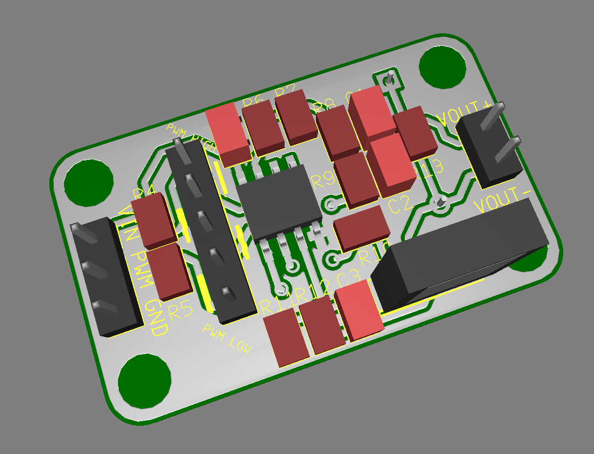
Besides minor cosmetic changes, I've added a jumper column to select PWM active high or active low with two jumpers. You can put the pins and jumpers or just solder it fixed. The silkscreen guides you about which ones to short por PWM active HIGH or PWM active LOW. PCB now is a bit bigger, but I think is worth it.
Any comments before I launch the order?
-
Nice work! Could you perhaps add a surface mount pad to the diode so the same board can accommodate both the through hole and surface mount part?
-
@gaweyo said in Designing a PWM to Analog mini board for fans:
Nice work! Could you perhaps add a surface mount pad to the diode so the same board can accommodate both the through hole and surface mount part?
Good idea!
-
@Egon-Net said in Designing a PWM to Analog mini board for fans:
Any comments before I launch the order?
Are you going to have someone install the parts? Or at least the SMDs?
Frederick
-
@fcwilt said in Designing a PWM to Analog mini board for fans:
@Egon-Net said in Designing a PWM to Analog mini board for fans:
Any comments before I launch the order?
Are you going to have someone install the parts? Or at least the SMDs?
Frederick
I'll do it by myself, I have a hot air soldering station and I've build many smd boards already.
BTW, @gaweyo, I've just added the smd diode footprint
-
@Egon-Net said in Designing a PWM to Analog mini board for fans:
I'll do it by myself, I have a hot air soldering station and I've build many smd boards already.
That's a skill I have never tried. I have a hot air soldering station but the project I purchased it for got canceled.
So there it sets new and unused.
How much are you going to be selling them for - say 25 units.
Frederick
Printers: a small Utilmaker style, a small CoreXY and a E3D MS/TC setup. Various hotends. Using Duet 3 hardware running 3.4.6
-
@fcwilt said in Designing a PWM to Analog mini board for fans:
@Egon-Net said in Designing a PWM to Analog mini board for fans:
I'll do it by myself, I have a hot air soldering station and I've build many smd boards already.
That's a skill I have never tried. I have a hot air soldering station but the project I purchased it for got canceled.
So there it sets new and unused.
How much are you going to be selling them for - say 25 units.
Frederick
I haven't calculated costs yet, but I my plan is just sharing the costs, just not to loose with each board. Once I have the prototype board working, I'll put a price for the DIY kit (board+components), just the bare PCB, and the complete mounted and tested board. And of course, I can send the gerbers for free too.
Would kind of kit would you need? Bare, components kit, mounted...?
-
@Egon-Net said in Designing a PWM to Analog mini board for fans:
Would kind of kit would you need? Bare, components kit, mounted...?
As busy as I am I would prefer completely assembled units - ready to install in a printer.
And you should price them to make some profit.
Frederick
-
@fcwilt said in Designing a PWM to Analog mini board for fans:
That's a skill I have never tried. I have a hot air soldering station but the project I purchased it for got canceled.
You can try one of those practice kits instead. https://www.aliexpress.com/item/32909277203.html
A solder iron, flux paste, and solder are all you need. A cheap Chinese stereoscopic optical microscope makes even easier.
-
@zapta said in Designing a PWM to Analog mini board for fans:
You can try one of those practice kits instead. https://www.aliexpress.com/item/32909277203.html
Great idea.
A solder iron, flux paste, and solder are all you need. A cheap Chinese stereoscopic optical microscope makes even easier.
I actually have all of those.
Frederick
-
@Egon-Net, one option you have is ordering assembled from vendors such as JLCPCB.
https://jlcpcb.com/smt-assembly
You may need to make design changes to reduce cost and use their standard parts. https://jlcpcb.com/parts
https://www.youtube.com/results?search_query=jlcpcb+assembly
Just an idea.
-
@zapta said in Designing a PWM to Analog mini board for fans:
@Egon-Net, one option you have is ordering assembled from vendors such as JLCPCB.
https://jlcpcb.com/smt-assembly
You may need to make design changes to reduce cost and use their standard parts. https://jlcpcb.com/parts
https://www.youtube.com/results?search_query=jlcpcb+assembly
Just an idea.
I don't think we are going to do so many boards to be an advantage. For the time being I will do the boards by myself, but maybe in the future I'm overwhelmed by all the people wanting the boards and I have to look something like that!

BTW, I'm already a costumer of JLCPCB