Very confused with Duet mesh level correction
-
@singhm29 said in Very confused with Duet mesh level correction:
; Z-Probe
M950 S0 C"io7.out" ; create servo pin 0 for BLTouch
M558 P9 C"^io7.in" H5 F120 T6000 ; set Z probe type to bltouch and the dive height + speeds ORIGINALI'm no expert for BLTouch. Is it the usual way to define 'io7' as in- and output?
-
@o_lampe said in Very confused with Duet mesh level correction:
@singhm29 said in Very confused with Duet mesh level correction:
; Z-Probe
M950 S0 C"io7.out" ; create servo pin 0 for BLTouch
M558 P9 C"^io7.in" H5 F120 T6000 ; set Z probe type to bltouch and the dive height + speeds ORIGINALI'm no expert for BLTouch. Is it the usual way to define 'io7' as in- and output?
Yes that's ok. The Duet 3 has a range of generalized io ports.
-
@singhm29 said in Very confused with Duet mesh level correction:
M906 X950 Y1900 Z950:950 E950 I30 ; set motor currents (mA) and motor idle factor in per cent
You only need to define a single value for Z. It will be applied to all drivers assigned to that axis. It's only for multiple extruders that the values must be defined for each, since extruders are independant.
-
@singhm29 said in Very confused with Duet mesh level correction:
X axis endstop is on the print head and homes to the minimum
Y axis endstop is in the back left corner and homes to a maximum
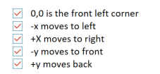
Z axis endstop is the BLtouch which homes to a minumumJust to be perfectly clear can you confirm that 0,0 is at the front left corner, -x moves to the left, +x to the right, -y to the front, +y to the back?
-
@singhm29 said in Very confused with Duet mesh level correction:
G28 ; home G30 P0 X0 Y300 Z-99999 ; probe near a leadscrew, half way along Y axis G30 P1 X600 Y300 Z-99999 S2 ; probe near a leadscrew and calibrate 2 motors
In bed.g you may want to add a G30 at the center of the bed after the sides have been probed and the tilt adjusted, because the act of changing the tilt can have an effect on the position of Z0. You may also want to double up on the tilt correction by adding a second pass.
G28 ; home G90 G30 P0 X0 Y300 Z-99999 ; probe near a leadscrew, half way along Y axis G30 P1 X600 Y300 Z-99999 S2 ; probe near a leadscrew and calibrate 2 motors G1 X300 Y300 F4000 ; go to first probe point G30 ; home Z by probing the bed G30 P0 X0 Y300 Z-99999 ; probe near a leadscrew, half way along Y axis G30 P1 X600 Y300 Z-99999 S2 ; probe near a leadscrew and calibrate 2 motors G1 X300 Y300 F4000 ; go to first probe point G30 ; home Z by probing the bed -
@singhm29 said in Very confused with Duet mesh level correction:
G29 ; mesh bed leveling G29 S1
The second G29 S1 is redundant. I don't think it would cause a problem, but once the G29 is performed the mesh is active, so no need to load the saved mesh afterwards.
-
Make those corrections and see how it goes.
Also keep in mind that the 2 point tilt correction is only going to correct for tilt along the X axis. You'll still need to manually level the bed to eliminate any tilt on the Y axis as much as possible for mesh compensation to be most effective.
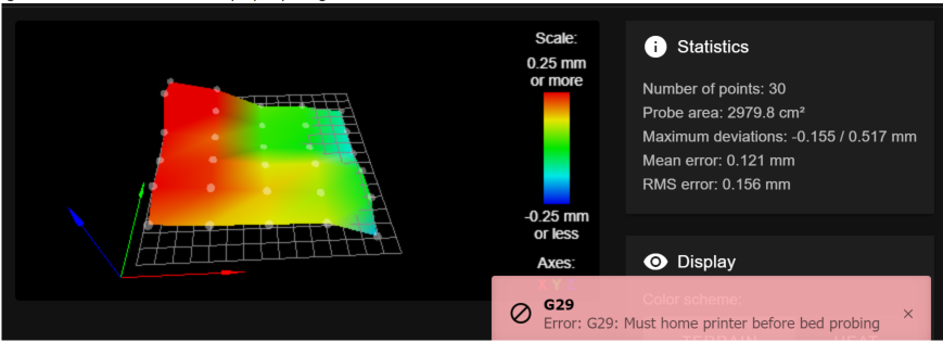
Your heightmap image indicates that there is a strong downward tilt back to front. That may be the bed tilting, but it may also be the XY gantry tilting down towards the back. Check the frame for squareness.
-
Thanks for the feedback. All changes were made other than changing any hardware yet.
Confirmed movement

Result from G29 without running G32

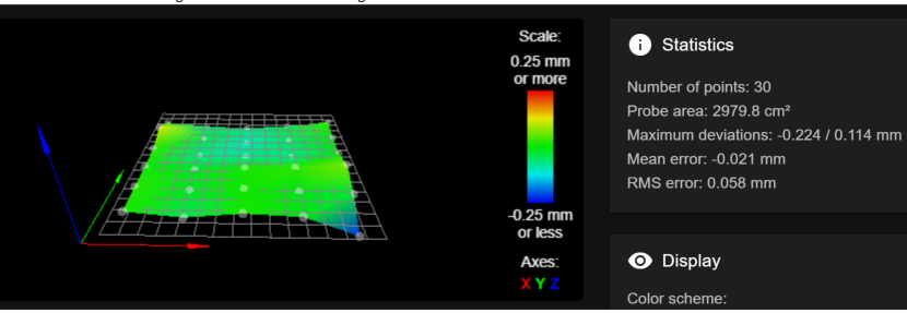
Result from G32 followed by G29

Other interesting things I observed
-when running G29 it skips the first row because the Bltouch would end up trying to probe off the bed

-after this I homed to center and again set to Z=0, the distance was no longer 1 paper sheet but a much larger distance
In terms of bed tilt along the Y axis I'm trying to imagine how I would correct that, normally if I have a bad nozzle crash I will move down the Z axis to the lowest point turn off stepper motors and then manually move down until my bed rests on both Z axis stepper motors to equal out both sides. I feel like that would correct X axis skew and help Y axis but im not sure after that what I could change...I guess I could also verify that there is actually tilt occuring by manually leveling the bed and turning off any compensation and seeing if jogging the Z axis up and down results in a change of Z distance between the front and back?
-
@singhm29 said in Very confused with Duet mesh level correction:
I guess I could also verify that there is actually tilt occuring by manually leveling the bed and turning off any compensation and seeing if jogging the Z axis up and down results in a change of Z distance between the front and back?
Yes that would be a good test. Is that large amount of tilt at the bed, or in the gantry?
-
I wasn't too sure if it was the gantry or the bed so I tried correcting both.
Here was my bed level before doing any changes to the physical bed.

Here it was after I loosened the bed corners so that the springs were all completely loose and then I moved the gantry to rest on the steppers at the bottom of the Z axis (equalizing the Z gantry tilt from left to right and back to front). From here again I set the Z probe offset which changed from 2.5 to 3.1mm. Here is what I got from that

Not particularly promising...so being humble I decided to give another go at bed leveling manually. Here is the result from that

Now to give some context I am not new to bed leveling manually as I have been printing since 2015 but here what was really baffling.
I turned off G29, G32 and G29 S1 from my start gcode printed for a round and the first layer came out well.
I turned on G29 and G32 and lo and behold with no physical changes to the bed I now had this

Thinking it was possibly the presence of G29 followed by G29 S1 I turned it back on to see if that would cause an issue. Again the new bed level came out great.

So I am back to a good looking bed but I have no idea how it was fixed. I'm hoping this will stick and wont be doing any physical changes. Lets see how long this lasts! Open to any thoughts but either way appreciate walking me through the possible issues.