New heated enclosure printer
-
@mrehorstdmd said in New heated enclosure printer:
Now the extruder carriage motion is going to try to pull 2m of filament off the spool at 200 mm/sec
Why?
If you consider a situation where the printhead is not printing (filament speed at stepper is 0), the carriage is moving from close to the spool to an extreme position, and the teflon tube is fixed at the spool box and the printhead, how can any filament be pulled off the spool? The filament already occupies the full length of the teflon tube, which does not change length. This is the reason to use a feed tube for the filament. The teflon tube changes in shape from a tall arch when the printhead is near the spool and a squat arch when it is far away, but the arc length of the arch remains the same so all the spool ever sees is the filament feed requirement.
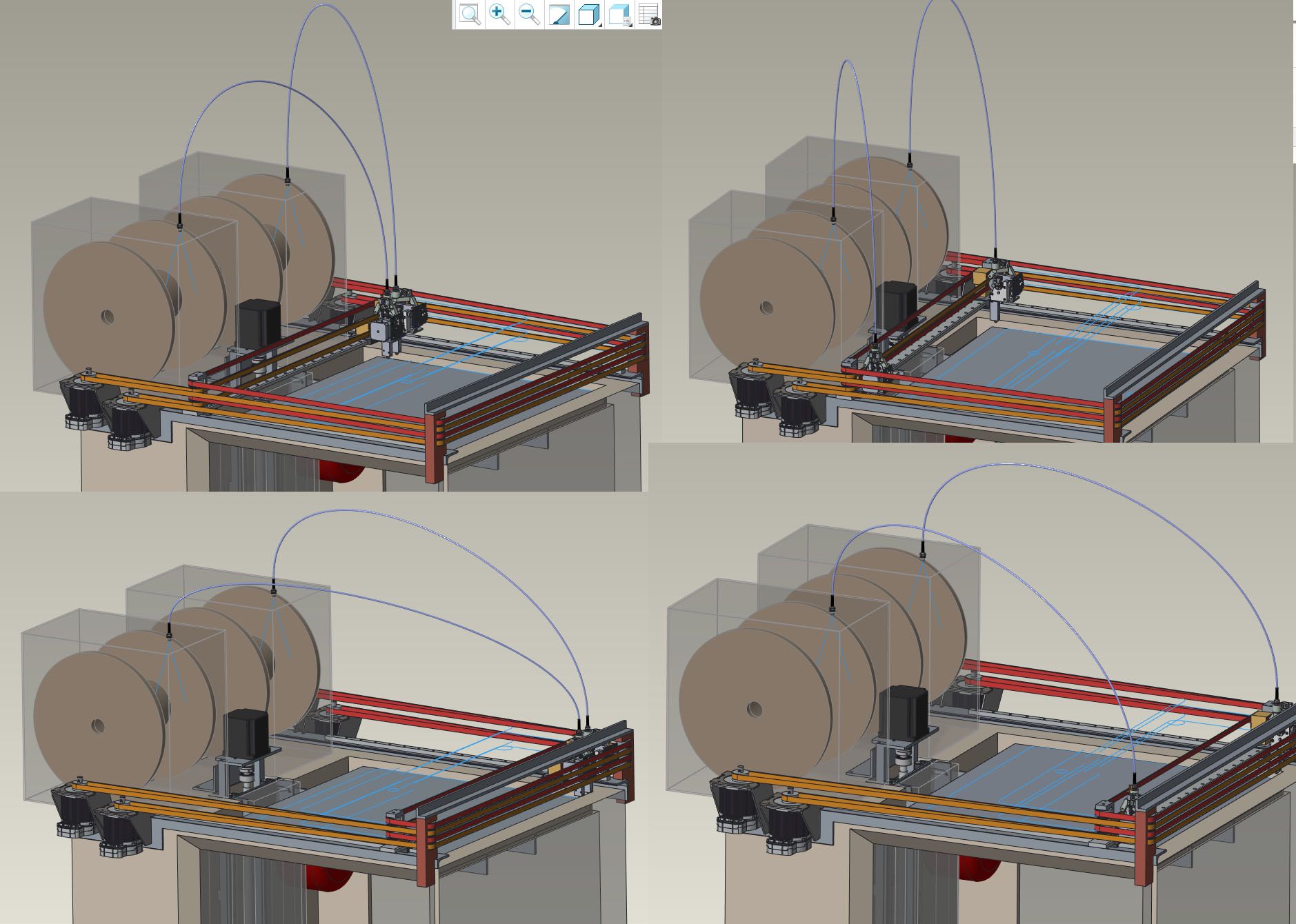
Adding whatever filament speed is needed for printing does not change the situation.If you have a spool above the printhead feeding down into the center of travels and the feed is a bare filament from the exit of the spool to the printhead, this exposed length of filament does change (pythagorean theorem) as the printhead moves and this would contribute directly to filament tension, causing spool rotation when the distance increases and spool slack when it decreases. This may not make much of a difference on smaller spools, but I think with a 10kg spool it would be a problem.
Chris
Cosentino Engineering -
@coseng I hadn't considered the use of the tube that way. Interesting. It's actually the opposite of what I was thinking. I'll have to look into a redesign of the feed in my printer. Thanks!
-
I have a similar feed tube and it works great. Never any tugging on the spool. Just smooth extruder pull. I have the tube open at the print head end to allow retractions to just push the tube back a bit rather than push the filament back in the tube. I've seen it called a reverse bowden tube before.
-
@phaedrux It's looks so obvious now. It's weird how some things just don't register. Getting old...
-
This is exactly what I do on my large printers - Predefine the filament length between box and head, to separate motion from filament travel. well done.
-
@mrehorstdmd A few years ago I had a client project that needed a swappable fiber optic switchboard and we went through several design iterations with and without feed tubes before getting one without feed tubes and with a spring loaded retract system that worked for ~1M cycles. So I've a bunch of relevant experience with the situation!

-
Sorry not to update more but a bit busy on other parts of the bike project. The bellows from Centryo came in and looks nice as did some waterjet cut parts for the XYUV motor mounts.

I'll try to get the Z axis armature fabricated this weekend, then next week my helper will start laying out the PCBs on a panel so that we can power up and test axis by axis as they are installed.
Chris
Cosentino Engineering -
Also forgot to ask if a thermistor (leftover from hot ends when replaced by PT1000) is good for a chamber sensor. I was going to connect two in series for the reading but was unsure if the housing was too much thermal mass to make it responsive enough.
Any suggestions on locations?
-
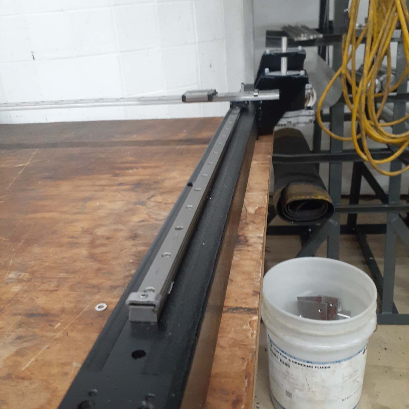
The Z axis fixture is mostly fabricated, it needs to be welded up then the linear rails shimmed into alignment.

The steel channel will be faced to clean it up, then the short arms will serve as mounts for the Z carriage assembly.

This will be some high temp CF sheet bonded/riveted together to provide a box-like structure that the build plate will sit on with a 3 point support system. The middle point (X0) will be a spherical bolted joint to provide a fixed point. The second support point will have a pin in a groove aligned with the fixed support to allow linear expansion but no rotation. The third point will be a plain support. This configuration should give the build plate repeatable thermal behavior.
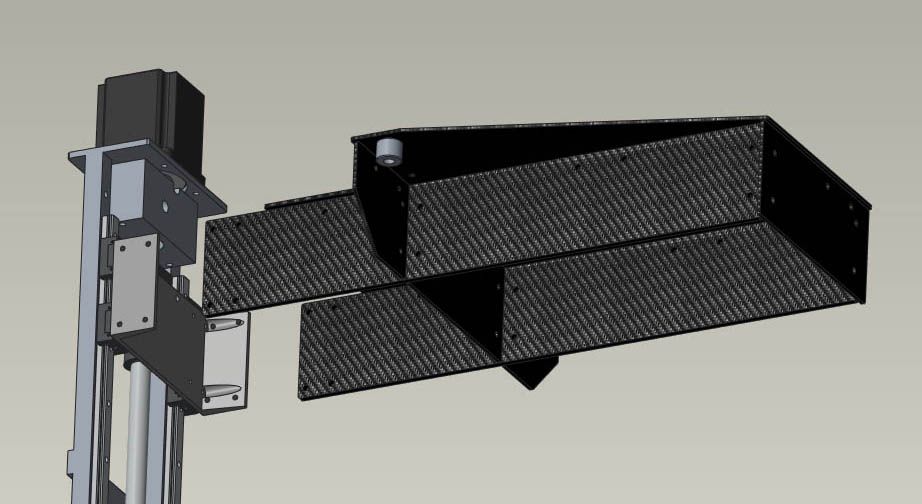
The two horizontal arms will fit through two slots in the insulation so the only parts in the heated chamber will be the CF assembly, which should minimize thermal growth issues.
Next week should see this completed and the XYUV assemblies started.
-
Awesome project! I'm looking forward to seeing it all come together. I am curious, why did you choose to have the Z axis rails inside the chamber rather than putting a slit into the rear wall and running the cantilevered bed supports through the wall?
-
@lael said in New heated enclosure printer:
I am curious, why did you choose to have the Z axis rails inside the chamber rather than putting a slit into the rear wall and running the cantilevered bed supports through the wall?
The insulation was not shown in the image but those spars are going through slots in the insulation to keep them out of the heated chamber.
-
@coseng Can't wait to see it completed! What reference points did you use for working out how to route and design the CoreXY IDEX?
-
@lael said in New heated enclosure printer:
@coseng Can't wait to see it completed! What reference points did you use for working out how to route and design the CoreXY IDEX?
Thanks! Me too, glad to be into the mechanics of it which means tweaking is not far away. I did a bunch of internet research and when I came across @mrehorstdmd's explanation of his Core XY layout, I didn't see any reason to reinvent the wheel so used it with minor adjustments for fitting to my enclosure.
-
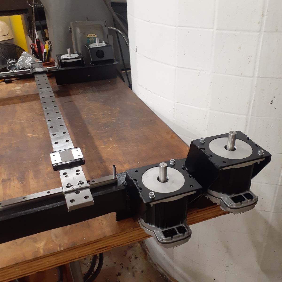
I finished most of the fab on the XYUV axis assembly and just have top weld up some adjustable mounting brackets to weld to the top of the enclosure.
So far so good with the rough alignment and the X axis rail seems stiff enough on its own.
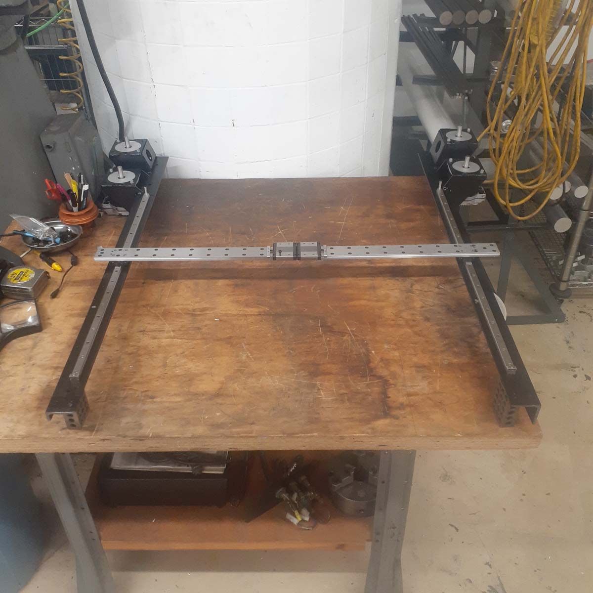
Its about to start getting together pretty quickly, then commissioning and setup of the Duet Hardware happens.
-
Some more progress on the XYUV axis assembly with bracing done and XY belts installed. I made all the long braces from steel to match expansion rates with the linear motion components. This thing will move around enough when it heats up, I'd rather not have to deal with twisting due to differential thermal expansions.
A little tweaking is needed to keep the belts happy but nothing major. Not sure if I will need some idler pulleys on the long runs to prevent vibrations. Now it is just sitting on top of the enclosure and points are being marked to weld in the mounting/alignment system.

-
I have a little paid client work coming in for the first time (yea!) in a while so printer fab is delayed a little (boo!).
In the meantime, I am doing a little thinking about the build surface and how removing large prints with lots of support and a raft/brim could be a bit difficult, to say the least.
Right now my plan for the build plate is a 5/16" thick piece of cast aluminum tooling plate with a full size Keenovo heater/silicone foam insulation stuck to the bottom and a 3 point support to the Z axis carriage.
I have (4) sheets of 350mm square PEI self adhesive film that was going to be used as the final build surface but I am thinking twice about that. One possibility is to put the PEI film on some thin aluminum sheet that would then be edge clamped onto the 5/16" aluminum plate. I'm trying to achieve the results like flexible steel build plates for resin printers provide.
Any thoughts/ recommendations?
-
@coseng A number of people are having great success with high temp garolite - NEMA G14. Good adhesion across a number of materials using PVP glue stick. It's relatively cheap for high temp work and is durable. The other option is Carbon Fibre, which visionminer popularised, just make sure the epoxy binders used are high temp rated as most CF is low temp rated epoxy. I haven't tried G14 yet, but G11 works wonders for Nylon and works well for PC. I haven't tried much ABS, but it was fine, I wouldn't say excellent. I can try some more in the near future for you if you are interested. G11 needs a surface sand with 180grit prior to use to get a dull surface, then a thin layer of PVP gluestick. G11 and G14 are both less stiff than CF plate.
https://www.mcmaster.com/3909N23/grade~g-14/ultra-high-temperature-impact-resistant-garolite-sheets/
https://www.mcmaster.com/8181K16/ - note temp rated to 190F / 90C, which is unlikely to suffice. However, is 3x the price.
Looking at the data, it looks like CF has 90-140,000psi flexural strength vs 45-60,000 for G14 and G11 is 42-58,000 by comparison. I would suggest 6mm / 1/4" if you go the garolite path.
-
@lael I'm not concerned so much with getting it to stick while printing as getting it to unstick when done. Lots of people have good results with ABS using a PEI build sheet, but most of those printers have removable build plates which make removal a lot easier if it does not pop off when cooling and contracting. Due to the size, heater, etc., my build plate main structure is fixed in the machine so I have to get the print off without too much strenuous activity or make a removable secondary layer that does not inhibit heat flow.
-
@coseng yep, that's fair. I think most materials won't inhibit heat flow that much. CF and CF are insulators, but that just means they take a couple of mins to get to temp. Once they are at temp, they maintain it fine.
In terms of plates, I would think removable would make life easier, regardless of what that is, unless the plate is wider than the door
")
-
@lael said in New heated enclosure printer:
@coseng yep, that's fair. I think most materials won't inhibit heat flow that much. CF and CF are insulators, but that just means they take a couple of mins to get to temp.
Well, not really. A temperature is one thing, but in a 3D printing situation we are more concerned with heat (energy) flow, which is driven by a temperature difference and limited by thermal resistance of the materials it is being transmitted through. With a thermally isolating build plate material you would need a higher build plate temperature to be able to get the same energy transfer to the part being built.
Once they are at temp, they maintain it fine.
That's because they do not want to give up the energy they were just given! And that is a problem because we are only heating the build plate to get heat (energy) into the part being built.
That is why I am surprised that the popular nozzle material is brass. Yes, it is easy to machine but it also a relatively poor thermal conductor and significantly limits the amount of heat that can be transferred from the heating element to the filament inside the nozzle bore, which limits the melt rate, which limits the overall print rate.
In terms of plates, I would think removable would make life easier, regardless of what that is, unless the plate is wider than the door
Yes, I agree. The aluminum plate can't come out because the heater and its wires are glued to the bottom. That's why I was thinking a secondary thin aluminum sheet with the PEI on it could be removed and not limit heat transfer from the plate into the part.