New heated enclosure printer
-
Nice. I'm using a Funmat HT right now at work that can go up to 90c chamber. ABS is sweet at 70c
-
@3dpmicro said in New heated enclosure printer:
ABS is sweet at 70c
Nice to hear. I've got a pretty decent sum in this so far and am really hoping it is not a time/money pit!
-
Still making progress, the heated chamber is cut, lined, and just about done.

The next step is laying out the electronics and wiring in the side area. Here are the main connections:
75VDC/1200W power supply for ClearPath XYUV servo power
24VDC/480W power supply for Duet 6HC powerDuet 6HC mainboard
-24VDC power in
-CAN to (2) 1LC toolboards
-OUT_1 to SSR for bed heater
-OUT_2 to SSR for chamber heater/fans
-OUT_3 to E3D water cooler 12V fan
-OUT_4 to E3D water cooler 12V pump
-OUT_5 to internal chamber recirculation 12V fan
-IO_01234 to XYUVZ endstops
-IO_5 to power 5V of EBOB for step/direction output
-TEMP_0 to PT1000 sensor for heated bed
-TEMP_1 to two PT1000 sensors in series for heated enclosure
-DIY soldered connections to EBOB for step/direction
-PanelDue 7i.1LC XY head
-CAN line
-24VDC power in
-filament stepper motor
-filament sensor
-PT1000 sensor
-80W 24VDC heater
-BLTouch1LC UV head
-CAN line
-24VDC power in
-filament stepper motor
-filament sensor
-PT1000 sensor
-80W 24VDC heaterI think that covers it all.
The servos and steppers are outside of the heated chamber so should not have overheating issues but if so, I can use the 1LC fan output for a filament stepper fan and the servos have fan mounts on the heatsink that can be driven from the power supply.
The 5/16" ground aluminum build plate and Keenovo 3000W 220VAC heater with silicone foam insulation arrived and will be put aside until the Z mechanism is ready next week.

Final build volume is 700x644x1020.
The next plans are to install the electronics, power supplies, etc. and initial wiring in the side compartment. Then bolt the Z axis in, connect it, and do a rough commission and alignment, then bolt the XYUV in and do the same. Then dig in for some extended tweaking sessions!
-
OK, one small revision. I just ordered a Duet Tool Distribution Board to handle connecting the 24VDC and CAN lines to the two 1LC boards on the printheads. That makes wiring a little cleaner and allows for some easy future expansion.
-
Doing a little detail work and came across a potential problem. Its a big printer so I wanted to use a big spool, 5 or 10kg per extruder. The spools would be on top of the printer in a sealed box riding on ball bearings with a teflon tube and a (not shown in CAD) spring 'skyhook' to keep the filaments, water cooler lines, and wiring somewhat tidy and controlled.
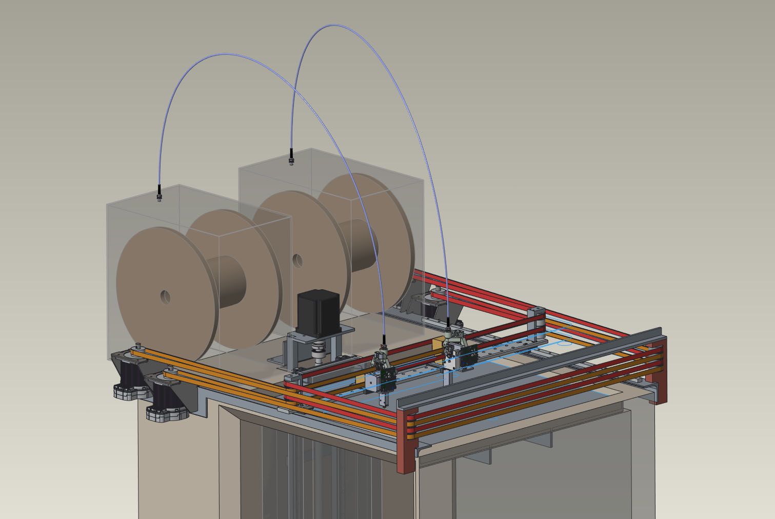
The filament direct drive is a E3D Titan Aqua with the standard stepper motor. A 10kg spool is a lot of mass to turn, and with the 50" or so of teflon tube will be a bit of friction in there. I'm thinking the filament drive motor may be hard pressed to keep up. There are two larger filament steppers available from E3D but I only have the 1.1A stepper driver on the 1LC toolboards to drive it. The 1LC is being fed with 24VDC.
Any thoughts on if I need to do something else here to prevent filament starvation problems?
-
@coseng Put the spools on ball bearing rollers (in or out of a box) mounted above the extruders, feeding straight down into them - no Teflon tubing and minimal pull strength required.
-
@mrehorstdmd I was trying to avoid making a high platform to hold 50-60lbs or so but it may be the best overall solution.
-
@coseng You're worried about the extruder pulling the filament, but you also have to worry about the XY motors. They'll be jerking at the spool as they move the extruder quickly around the bed. It's best to keep everything as close to the center of the bed and as short a path as possible, that way the jerking on the spool is minimized.
-
@mrehorstdmd With a teflon tube fixed at both ends (fixed length) how would the XY motors be tugging on the spools for anything more than drawing filament out? Without one there will definitely be tugging/slack which is possibly a reason not to do the top mount.
-
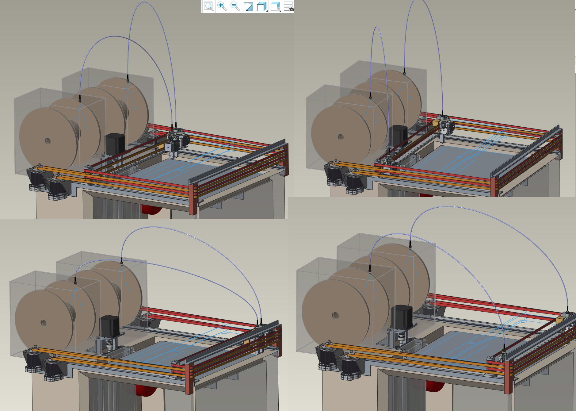
@coseng The extruder only pulls filament off the spool at a few mm/sec. Say the X axis is 2m long and the spool is at a fixed location near one end of the X axis. Now let's say the extruder is printing a layer of a part near the end of the X axis where the spool is located. When it finishes that layer on that part it has to travel to the other end of the X axis to print a layer on another part. Travel speed is set to 200 mm/sec. Now the extruder carriage motion is going to try to pull 2m of filament off the spool at 200 mm/sec. The XY motors are going to have to be able to accelerate the extruder carriage against the rotational inertia of the large filament spool (plus friction in the teflon tube). If they can't, you may get skipped steps.
Slicers generally place parts to be printed at the center of the bed, which means that most of the time the extruder carriage will be orbiting the bed center. That means that it's best to try to keep the spool over the center of the bed because it results in the shortest path between the spool and the extruder carriage, most of the time. If you must use a teflon tube to guide the filament (not sure why you would need to) to the extruder carriage, positioning the spool at the center of the bed will allow the shortest teflon tube to be used (assuming you feed the filament straight down to the extruder.
-
@mrehorstdmd said in New heated enclosure printer:
Now the extruder carriage motion is going to try to pull 2m of filament off the spool at 200 mm/sec
Why?
If you consider a situation where the printhead is not printing (filament speed at stepper is 0), the carriage is moving from close to the spool to an extreme position, and the teflon tube is fixed at the spool box and the printhead, how can any filament be pulled off the spool? The filament already occupies the full length of the teflon tube, which does not change length. This is the reason to use a feed tube for the filament. The teflon tube changes in shape from a tall arch when the printhead is near the spool and a squat arch when it is far away, but the arc length of the arch remains the same so all the spool ever sees is the filament feed requirement.
Adding whatever filament speed is needed for printing does not change the situation.If you have a spool above the printhead feeding down into the center of travels and the feed is a bare filament from the exit of the spool to the printhead, this exposed length of filament does change (pythagorean theorem) as the printhead moves and this would contribute directly to filament tension, causing spool rotation when the distance increases and spool slack when it decreases. This may not make much of a difference on smaller spools, but I think with a 10kg spool it would be a problem.
Chris
Cosentino Engineering -
@coseng I hadn't considered the use of the tube that way. Interesting. It's actually the opposite of what I was thinking. I'll have to look into a redesign of the feed in my printer. Thanks!
-
I have a similar feed tube and it works great. Never any tugging on the spool. Just smooth extruder pull. I have the tube open at the print head end to allow retractions to just push the tube back a bit rather than push the filament back in the tube. I've seen it called a reverse bowden tube before.
-
@phaedrux It's looks so obvious now. It's weird how some things just don't register. Getting old...
-
This is exactly what I do on my large printers - Predefine the filament length between box and head, to separate motion from filament travel. well done.
-
@mrehorstdmd A few years ago I had a client project that needed a swappable fiber optic switchboard and we went through several design iterations with and without feed tubes before getting one without feed tubes and with a spring loaded retract system that worked for ~1M cycles. So I've a bunch of relevant experience with the situation!

-
Sorry not to update more but a bit busy on other parts of the bike project. The bellows from Centryo came in and looks nice as did some waterjet cut parts for the XYUV motor mounts.

I'll try to get the Z axis armature fabricated this weekend, then next week my helper will start laying out the PCBs on a panel so that we can power up and test axis by axis as they are installed.
Chris
Cosentino Engineering -
Also forgot to ask if a thermistor (leftover from hot ends when replaced by PT1000) is good for a chamber sensor. I was going to connect two in series for the reading but was unsure if the housing was too much thermal mass to make it responsive enough.
Any suggestions on locations?
-
The Z axis fixture is mostly fabricated, it needs to be welded up then the linear rails shimmed into alignment.

The steel channel will be faced to clean it up, then the short arms will serve as mounts for the Z carriage assembly.

This will be some high temp CF sheet bonded/riveted together to provide a box-like structure that the build plate will sit on with a 3 point support system. The middle point (X0) will be a spherical bolted joint to provide a fixed point. The second support point will have a pin in a groove aligned with the fixed support to allow linear expansion but no rotation. The third point will be a plain support. This configuration should give the build plate repeatable thermal behavior.
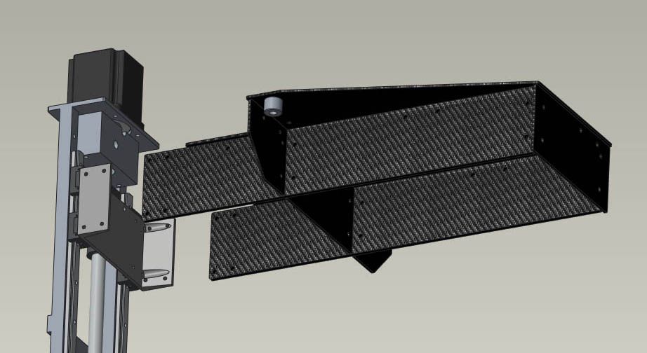
The two horizontal arms will fit through two slots in the insulation so the only parts in the heated chamber will be the CF assembly, which should minimize thermal growth issues.
Next week should see this completed and the XYUV assemblies started.
-
Awesome project! I'm looking forward to seeing it all come together. I am curious, why did you choose to have the Z axis rails inside the chamber rather than putting a slit into the rear wall and running the cantilevered bed supports through the wall?