Duet3D Logo Duet3D
    • Tags
    • Documentation
    • Order
    • Register
    • Login

    Is there a way to debug accelerometer connection issues?

    Scheduled Pinned Locked Moved Solved
    Beta Firmware
    7
    27
    2.1k
    Loading More Posts
    • Oldest to Newest
    • Newest to Oldest
    • Most Votes
    Reply
    • Reply as topic
    Log in to reply
    This topic has been deleted. Only users with topic management privileges can see it.
    • SIamundefined
      SIam @dc42
      last edited by

      @dc42 the white wire is the SCL pin

      Hypercube-Evolution-Hybrid, Piezo Orion, Orbiter
      Duet WiFi 1.02 or later + DueX5
      RepRapFirmware for Duet 2 WiFi/Ethernet 3.4.0beta4 (2021-09-27 11:30:36)
      Duet WiFi Server: 1.26
      Duet Web Control 3.4.0beta4 (2021-09-27)

      1 Reply Last reply Reply Quote 0
      • OwenDundefined
        OwenD @dc42
        last edited by

        @dc42 said in Is there a way to debug accelerometer connection issues?:

        PS - you initially had this according to the error message:

        M955 P0 C"spi.cs4+spi.cs3" ; configure accelerometer

        but your config.g has this:

        M955 P0 C"spi.cs3+spi.cs4" ; configure accelerometer

        Which are you using? I think spi.cs3+spi.cs4 is correct for your wiring scheme.

        I had originally tried M955 P0 C"spi.cs3+spi.cs4" per my config.
        When I was running out of ideas, I tried reversing it. I must have picked up the error message from the latter.

        This breakout board has QT connections available. Otherwise it's identical.

        OK, I see the pin connection now. Is that the newer version of the Adafruit board? What >is the pin between GND and SDA (white wire)?

        The pin between VIN and GND says 3V. I had been using VIN, but as that would be 5V on the arduino and 3V on the duet, I just tried again using the 3V pin.
        Same result. Unit powers up, but is not found.
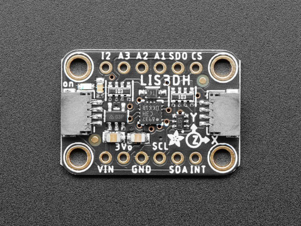
        LIS3DH.jpg

        Data sheet
        https://cdn-learn.adafruit.com/assets/assets/000/085/846/original/lis3dh.pdf?1576396666

        Schematic
        https://learn.adafruit.com/assets/94435

        The data sheet says that the CS pin must be brought low to enable SPI and it defaults to I2C
        Could this be the issue?

        dc42undefined 1 Reply Last reply Reply Quote 0
        • dc42undefined
          dc42 administrators @OwenD
          last edited by

          Have you tried using a different Duet pin to connect CS to? E.g. spi.cs1

          Duet WiFi hardware designer and firmware engineer
          Please do not ask me for Duet support via PM or email, use the forum
          http://www.escher3d.com, https://miscsolutions.wordpress.com

          OwenDundefined 1 Reply Last reply Reply Quote 0
          • OwenDundefined
            OwenD @dc42
            last edited by OwenD

            @dc42 said in Is there a way to debug accelerometer connection issues?:

            Have you tried using a different Duet pin to connect CS to? E.g. spi.cs1

            Just tried it.
            Moved green wire (CS) to spi.cs1
            IMG-1860.jpg

            Same result.
            Screenshot_2021-05-01 3Dprinter.png

            On a side note, there seem to be two wiring diagrams floating around.
            One says it's CS1 and the other CS0

            https://d17kynu4zpq5hy.cloudfront.net/igi/duet3d/JPWtqVWwLBxCAKyP.huge

            https://d17kynu4zpq5hy.cloudfront.net/igi/duet3d/vqBUAZPsxMC5tRgt.huge

            The one that says CS0 can be found here
            https://duet3d.dozuki.com/Guide/2.)+Wiring+your+Duet+2+WiFi-Ethernet/9

            1 Reply Last reply Reply Quote 0
            • OwenDundefined
              OwenD
              last edited by

              OK.
              I just tried wiring directly to the LIS3DH using 150mm jumpers and it works!
              Screenshot_2021-05-01 3Dprinter(1).png

              Strange that the other cable works on an arduino.

              Would it be better to use cable that has twisted pairs?
              I thought the shielded cable would be a good option.

              Diamondbackundefined 1 Reply Last reply Reply Quote 0
              • Diamondbackundefined
                Diamondback @OwenD
                last edited by

                @owend What kind of cable are you using? Another user and I had good success with USB 3 cables (mine is 3m long).

                OwenDundefined tekstyleundefined 2 Replies Last reply Reply Quote 0
                • OwenDundefined
                  OwenD @Diamondback
                  last edited by

                  @diamondback
                  I was using 9 core shielded
                  https://www.altronics.com.au/p/w2712-9-core-shielded-data-cable/

                  I'm about to try some CAT5 data cable (4 x twisted pairs)
                  I'll report back.

                  Diamondbackundefined 1 Reply Last reply Reply Quote 0
                  • Diamondbackundefined
                    Diamondback @OwenD
                    last edited by Diamondback

                    @owend Ok, I tried single twisted pairs first, ie basically the inner part of CAT 5 cable without any shielding, and that didn't work for me. The USB cable is both twisted and shielded multiple times, I connected all the shielding to GND as well.

                    1 Reply Last reply Reply Quote 0
                    • OwenDundefined
                      OwenD
                      last edited by OwenD

                      Success!
                      For me a piece pf CAT5E cable worked.
                      I'm reasonable confident the connections on the first cable are sound.
                      Perhaps a better choice would be the USB cables suggested or maybe CAT6 shielded cables?

                      Now I have some data...
                      Just have to work out what to do with it 🙄

                      Diamondbackundefined zaptaundefined 2 Replies Last reply Reply Quote 0
                      • Diamondbackundefined
                        Diamondback @OwenD
                        last edited by

                        @owend said in Is there a way to debug accelerometer connection issues?:

                        Success!
                        For me a piece pf CAT5E cable worked.
                        I'm reasonable confident the connections on the first cable are sound.
                        Perhaps a better choice would be the USB cables suggested or maybe CAT6 shielded cables?

                        Now I have some data...
                        Just have to work out what to do with it 🙄

                        Awesome! 👏

                        1 Reply Last reply Reply Quote 0
                        • zaptaundefined
                          zapta @OwenD
                          last edited by

                          @owend said in Is there a way to debug accelerometer connection issues?:

                          Perhaps a better choice would be the USB cables suggested or maybe CAT6 shielded cables?

                          An oscilloscope would allow you to look at the signals and see if they are missing or distorted.

                          OwenDundefined 1 Reply Last reply Reply Quote 0
                          • OwenDundefined
                            OwenD @zapta
                            last edited by

                            @zapta said in Is there a way to debug accelerometer connection issues?:

                            An oscilloscope would allow you to look at the signals and see if they are missing or distorted.

                            True. But out of the reach of many of us.
                            In my original post topic I was hoping that RRF could somehow self diagnose communication on each pin.
                            It seems like it's going to be pretty critical to get cables just right for this to work.

                            zaptaundefined 1 Reply Last reply Reply Quote 0
                            • zaptaundefined
                              zapta @OwenD
                              last edited by

                              @owend said in Is there a way to debug accelerometer connection issues?:

                              True. But out of the reach of many of us.

                              That's correct. Digital oscilloscope prices went down very significantly but it's still a significant amount of money.

                              I was hoping that RRF could somehow self diagnose communication on each pin.

                              Let's see if future generations of Duet boards will have an accelerometer connector that will work out of the box with the optional Duetcelerometer module. 😉

                              dc42undefined 1 Reply Last reply Reply Quote 0
                              • dc42undefined
                                dc42 administrators @zapta
                                last edited by

                                I have made the accelerometer SPI clock frequency configurable and reduced the default from 4MHz to 2MHz. I expect this will make it easier to obtain a connection. These changes will be in RRF 3.3RC1.

                                Duet WiFi hardware designer and firmware engineer
                                Please do not ask me for Duet support via PM or email, use the forum
                                http://www.escher3d.com, https://miscsolutions.wordpress.com

                                1 Reply Last reply Reply Quote 0
                                • clownsracheundefined
                                  clownsrache
                                  last edited by clownsrache

                                  What kind of issue do i have?

                                  1.5.2021, 15:42:23: M955 P0 C"spi.cs2+spi.cs3": Accelerometer 0:0 with orientation 20 samples at 1344Hz with 10-bit resolution

                                  M956 P124.0 S10 A0

                                  1.5.2021, 15:45:43: M98 P"0:/macros/ACC": Error: Response timeout: CAN addr 124, req type 4014, RID=0

                                  dc42undefined 1 Reply Last reply Reply Quote 0
                                  • dc42undefined
                                    dc42 administrators @clownsrache
                                    last edited by

                                    @clownsrache after sending that M955 command, what does M955 without parameters respond with?

                                    Duet WiFi hardware designer and firmware engineer
                                    Please do not ask me for Duet support via PM or email, use the forum
                                    http://www.escher3d.com, https://miscsolutions.wordpress.com

                                    dc42undefined 1 Reply Last reply Reply Quote 0
                                    • dc42undefined
                                      dc42 administrators @dc42
                                      last edited by

                                      RRF 3.3RC1 with configurable accelerometer SPI frequency is now available at https://github.com/Duet3D/RepRapFirmware/releases/tag/3.3RC1.

                                      Duet WiFi hardware designer and firmware engineer
                                      Please do not ask me for Duet support via PM or email, use the forum
                                      http://www.escher3d.com, https://miscsolutions.wordpress.com

                                      1 Reply Last reply Reply Quote 0
                                      • tekstyleundefined
                                        tekstyle @Diamondback
                                        last edited by

                                        @diamondback how would u use a USB cable? it only has 4 wires but we need 7 for the adafruit accelerometer

                                        dc42undefined Diamondbackundefined 2 Replies Last reply Reply Quote 0
                                        • dc42undefined
                                          dc42 administrators @tekstyle
                                          last edited by

                                          @tekstyle I have had good results with ribbon cable, ensuring that the CS wire is not next to any other signal wires. See the images and description at https://duet3d.dozuki.com/Wiki/Accelerometers#Section_Direct_SPI_connection_to_a_Duet_main_board.

                                          Duet WiFi hardware designer and firmware engineer
                                          Please do not ask me for Duet support via PM or email, use the forum
                                          http://www.escher3d.com, https://miscsolutions.wordpress.com

                                          1 Reply Last reply Reply Quote 0
                                          • Diamondbackundefined
                                            Diamondback @tekstyle
                                            last edited by

                                            @tekstyle said in Is there a way to debug accelerometer connection issues?:

                                            @diamondback how would u use a USB cable? it only has 4 wires but we need 7 for the adafruit accelerometer

                                            Use an USB 3 cable 🙂 It has 8 wires.

                                            tekstyleundefined 1 Reply Last reply Reply Quote 0
                                            • First post
                                              Last post
                                            Unless otherwise noted, all forum content is licensed under CC-BY-SA