Z offset on Inductive sensors
-
Hi. Im using:
Board: Duet 3 MB6HC (MB6HC)
DSF Version: 3.2.2
Firmware: RepRapFirmware for Duet 3 MB6HC 3.2.2 (2021-02-11)Something is somehow wrong and I cant find what. Im very sure in previous version the zzoffset of my inductive probe was around 0.7 mm.
I followed the instructions provided by the wiki to find the Z offset :
https://duet3d.dozuki.com/Wiki/Using_mesh_bed_compensationI updated everything DWC and firmware using the apt update.upgrade procedure, now Im having this offset problem. I had to do a recalibration, the offset I found was 0.3, BUT when printing Im forced to do baby stepping to -0.3.
That means that my offset should be CERO, wich definitely is not OK since I can tell that the probe is 1.5 mm above the nozzle tip.
Is there any report of offset not being properly shown or something like that?
-
We'd have to see the config.g, homeall/homez, bed.g, and your slicer start gcode to get an idea of what's happening between when the printer is powered on and the print starts. As far as I'm aware there is no currently known problem with z offsets.
-
@phaedrux Sure:
Config.g
; Configuration file for Duet 3 (firmware version 3) ORIGINAL
; executed by the firmware on start-up
;; General preferences
G90 ; send absolute coordinates...
M83 ; ...but relative extruder moves
M669 K1 ; select CoreXY mode; Network
; M552 S0 ; disable network only betas; Drives
M569 P0.0 S0 D2 ; physical drive 0.0 goes forwards X
M569 P0.1 S1 D2 ; physical drive 0.1 goes forwards Y Ultimo cambio: de S0 a S1
M569 P0.2 S1 D2 ; physical drive 0.2 goes forwards
M569 P0.3 S1 D2 ; physical drive 0.3 goes reverse
M569 P0.4 S0 D2 ; physical drive 0.4 goes forwards
M569 P0.5 S1 D2 ; physical drive 0.5 goes backwardsM584 X0.0 Y0.1 Z0.2:0.3 E0.4:0.5 ; set drive mapping
M350 X16 Y16 Z16 E16:16 I1 ;configure microstepping with interpolation. Changed Z to 16 from 32M92 X80.16 Y80.16 Z1600 E428.25:428.25 ; set steps per mm changed Z from 3200 to 1600
M566 X1500.00 Y1500.00 Z300.00 E450:450 P0 ; set maximum instantaneous speed changes (mm/min) CAMBIO set policy to 1 instead of CERO CAMBIO jerk de 900 a 1200 para X e Y. Change policy 1 to policy 0
M203 X18000.00 Y18000.00 Z340.00 E2400.00 ; set maximum speeds (mm/min)
M201 X3000 Y3000.00 Z20 E1500.00 ; set accelerations (mm/s^2) CAMBIO < cambie de 1000 a 3000 a testear, extrusor cambio de 500 a 1500
M204 P2000 T3000
M906 X1500 Y1500 Z1200 E900:900 I30 ; set motor currents (mA) and motor idle factor in per cent
M84 S300 ; Set idle timeout; Axis Limits
M208 X0 Y0 Z0 S1 ; set axis minima
M208 X400 Y400 Z406 S0 ; set axis maxima; Endstops latest
M574 X1 S1 P"!io1.in" ; Endstop X Min
M574 Y1 S1 P"!io0.in" ; Endstop Y min
M574 Z2 S2 ; configure Z-probe endstop for low end on Z; Z-Probe
M558 P5 C"^!io3.in" H5 F120 T18000 ; set Z probe type to switch and the dive height + speeds
G31 P500 X-7 Y-29 Z0.3 ; set Z probe trigger value offset and trigger height
; M557 X25:310 Y27:312 S57:57 define mesh grid for beta 3
M557 X33:320 Y10:335 S41:25 ; define mesh beta4; Heaters
M308 S0 P"temp0" Y"thermistor" T100000 B4138 ; configure sensor 0 as thermistor on pin temp0
M950 H0 C"out0" T0 ; create bed heater output on out0 and map it to sensor 0
M307 H0 B1 S1.00 ; enable bang-bang mode for the chamber heater and set PWM limit
M141 H0 ; map chamber to heater 0
M143 H0 S130 ; set temperature limit for heater 0 to 130C
M308 S1 P"temp1" Y"thermistor" T500000 B4723 C1.19622e-7 ; configure sensor 1 as thermistor on pin temp1
M950 H1 C"out1" T1 ; create nozzle heater output on out1 and map it to sensor 1
M307 H1 B0 S1.00 ; disable bang-bang mode for heater and set PWM limit
M308 S2 P"temp2" Y"thermistor" T500000 B4723 C1.19622e-7 ; configure sensor 2 as thermistor on pin temp2
M950 H2 C"out2" T2 ; create nozzle heater output on out2 and map it to sensor 2
M307 H2 B0 S1.00 ; disable bang-bang mode for heater and set PWM limit; Tools
M563 P0 D0 H1 ;define tool 0
G10 P0 X0 Y0 Z0 ;set tool 0 axis offsets
G10 P0 R0 S0 ;set initial tool 0 active and standby temperatures to 0C
M563 P1 D1 H2 ;define tool 1
G10 P1 X-61 Y0 Z-2.05 ;set tool 1 axis offsets
G10 P1 R0 S0 ;set initial tool 1 active and standby temperatures to 0C; Custom settings are not defined
; movments without homing
; M564 H0; Miscellaneous
M207 S6 R0.2 F1800 ;firmware retraction
M83 ; relative extrusion
M950 S0 C"0.out9" ; servo "0" in pin out9
M280 P0 S115 ; move servo for T1 up default position
; M376 H30 cancell mesh levelling at 30 mm
M143 S450 ; set max temp to 450 degrees for T0
M143 H2 S450 ; set max temp to 450 for T1
M950 J0 C"^io8.in" ; Definition of emervengy stop pin
M581 P0 R0 T0 ; Assigment of the emergency stop
M950 P5 C"out3" ; assign gpio port 5 to out3 for buzzer. control with M42 P5 SX range 0 to 1
M671 X0:350 Y175:175 S3 ; set 2 probing points to correct any possible tilted bed
; M591 D1 P1 C"io5.in" S1 ; pin tapa superior stop
M950 J6 C"io5.in" ; define door pin stop
M581 P6 T2 S0 R1 ; set trigger2.g to be excuted if door opened while printing
M950 J7 C"io6.in" ; define top lid pin stop
M581 P7 T3 S0 R1 ; set trigger3.g to be excuted if door opened while printing
M671 X230:0 Y175:175 S5
M501 ; load saved parameters from non-volatile memory
T0 ; select first tool 0HOME ALL:
; homeall.g
; called to home all axes
;
M564 H0
M280 P0 S115
T0 P0
G91
G1 Z5
M564 H1
G90; HOME X/Y
G91 ; relative mode
G1 H1 X-400 F3000 ; coarse home X or Y
G1 H1 Y-400 F3000
G1 X4 Y4 F600 ; move away from the endstops
G1 H1 X-10 F80 ; fine home X
G1 H1 Y-10 F80 ; fine home Y
G90 ; absolute positioning; Z HOMING
; G1 X175 Y175 F5000 go to first bed probe point and home Z for beta3
G1 X135 Y100 F5000 ; production
M400
M913 Z30
G30
M400
M913 Z100HOME Z
; homez.g
; called to home the Z axisM400
M564 H0
M280 P0 S115
T0 P0
G91
G1 Z5
M564 H1
G90G1 X135 Y100 F5000
M400
M913 Z30
G30 ; home Z by probing the bed
M400
M913 Z100BED.G
; generated by RepRapFirmware Configuration Tool v3.1.4 on Wed Aug 19 2020 03:46:47 GMT-0300 (Argentina Standard Time)
M561 ; clear any bed transform
G28 ; home
G30 P0 X10 Y175 Z-99999 ; probe near left leadscrew
G30 P1 X350 Y175 Z-99999 S2 ; probe near right leadscrew and calibrate 2 motorsSTART GCODE OF SLICER
M104 S120
T0
M141 S100
M116 C0
G4 S120
M104 S{first_layer_temperature[0] -100}
M116
G28 X0 Y0
G28 X0 Y0
G28 Z0
G30; Home z again with probe
M400
G29
G4 S5
G29 S1
M141 S{chamber_temperature[0]}
M116
G4 S180
M42 P5 S0.2
G4 S2
M42 P5 S0
G10 S{first_layer_temperature[0]}
M116 -
Hi,
What materials are part of your bed structure?
What is the make and model of the probe?
Thanks.
Frederick
-
Inductive sensors are usually temperature-sensitive. Did you calibrate the sensor trigger height with the bed and hot end at printing temperature?
Duet WiFi hardware designer and firmware engineer
Please do not ask me for Duet support via PM or email, use the forum
http://www.escher3d.com, https://miscsolutions.wordpress.com -
@dc42 Yes, temperature calibrated. Also, while doing the offset calibration, I do it at the printing temperature.
My printing surface is metal, the sensor can detect 2mm away and the sensor it is 1.5 mm ABOVE the tip of the nozzle, so how can it be possible that the reported offset is 0.3? (or actually "cero" because that is what I have to baby step to have a good first layer) -
@tinchus said in Z offset on Inductive sensors:
M913 Z30
Are you maybe missing steps occasionally from reducing the z motor current too much?
-
@phaedrux the current reduction is only for the probing step, then current is retored to 100%
Also, Im using 30% but I hardly can stop the bed using my hand at that power. Both motors have a really strong arm. I did test and Im at risk of loosing steps at 20 %. So it is somehow not probable that im loosing steps at 30%.Still I did te test at 100% and the problem remains.
-
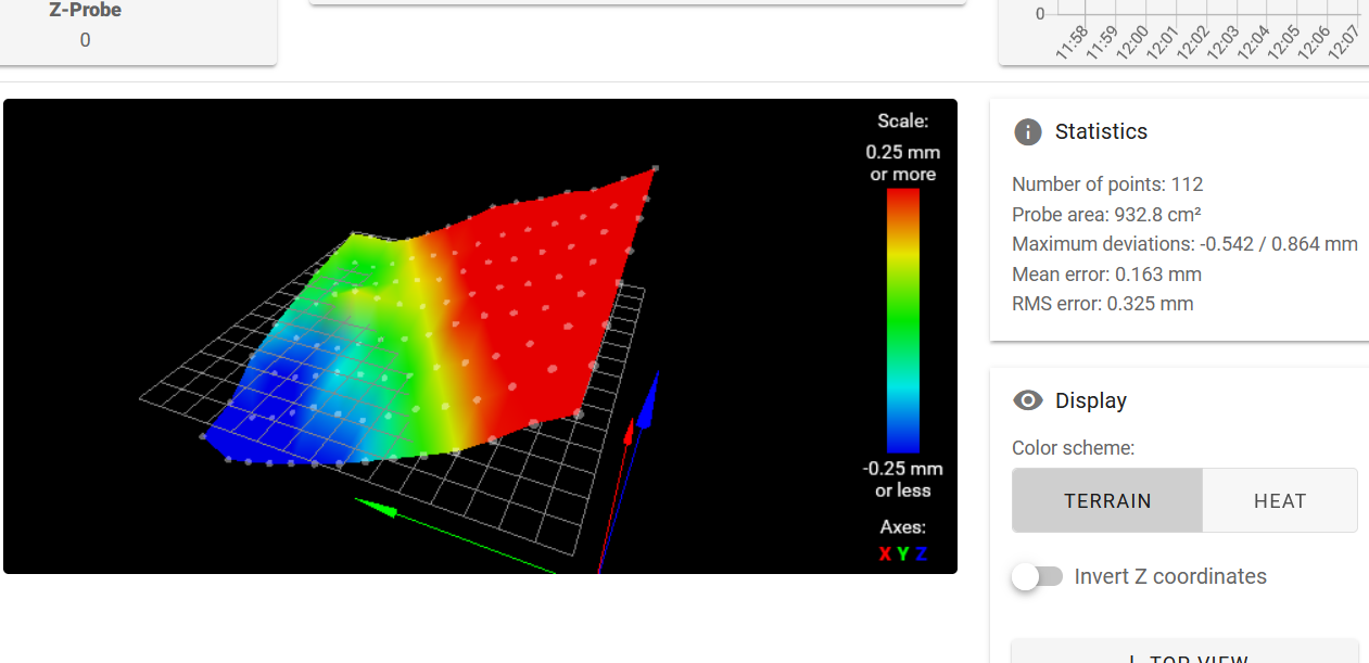
Can you post an image of what your mesh heightmap looks like displayed in DWC?
-
@tinchus said in Z offset on Inductive sensors:
the current reduction is only for the probing step, then current is retored to 100%
Out of curiosity why do you reduce the current?
Thanks.
Frederick
-
@fcwilt because I planned the printer to have eough power to have all the build plate full of print, and since it is a big volumen, theoretically I can have like 15 kgs if I print metal. So Z motors have enough power to move that mass.
BUT, if something goes wrong, the also have the power to destroy my hotenfd and bend the bed if the printhead crash against the bed at full powwer. By reducing to 30% while homing, if something goes wrong, they will start to loose steps before bending my bed. -
@tinchus said in Z offset on Inductive sensors:
So Z motors have enough power to move that mass.BUT, if something goes wrong, the also have the power to destroy my hotenfd and bend the bed
Wow.
What steppers are you using?
Thanks.
Frederick
-
@phaedrux This is just from the oven: heighmap with print chamber at 120 degrees celsius:
-
@tinchus said in Z offset on Inductive sensors:
This is just from the oven: heighmap with print chamber at 120 degrees celsius:
That is not good.
But it does make me feel better about mine.
")
At what XY point are you setting the Z=0 datum with G30 prior to creating the heightmap?
Thanks.
Frederick
-
That's quite a lot of tilt. On the bright side it looks like the surface itself is mostly flat. Is there anyway you can square the bed and gantry a bit better?
-
@phaedrux What you are looking is the normal deformation an aluinium bed will have under 120 degrees celsius + yes there is some tilt to the front.
-
-
@tinchus said in Z offset on Inductive sensors:
@phaedrux What you are looking is the normal deformation an aluinium bed will have under 120 degrees celsius + yes there is some tilt to the front.
If that is "normal" for your setup I think you need to change the design - that is a lot of tilt - you are talking about 7 to 14 layers of compensation required.
And the nozzle-to-bed relationship will likely have a negative effect on print quality.
-
@fcwilt You are loosing the focus: compensation is working OK. The problem is the Z offset reported, is not realistic.
-
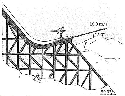
Try this, when measuring your G30 S-1 after touching down your nozzle to the bed, job the probe so that it's over that same point. If there is enough tilt there will be a difference in height between where the nozzle is and the probe is. Just like the triangle formed by the ski jumper leaving the ramp.