Automated Nozzle offset calibration for IDEX printers
-
I have an IDEX printer with quick swap hotends and every time I exchange a hotend I have to recalibrate the XY-Nozzle offsets with a test print.
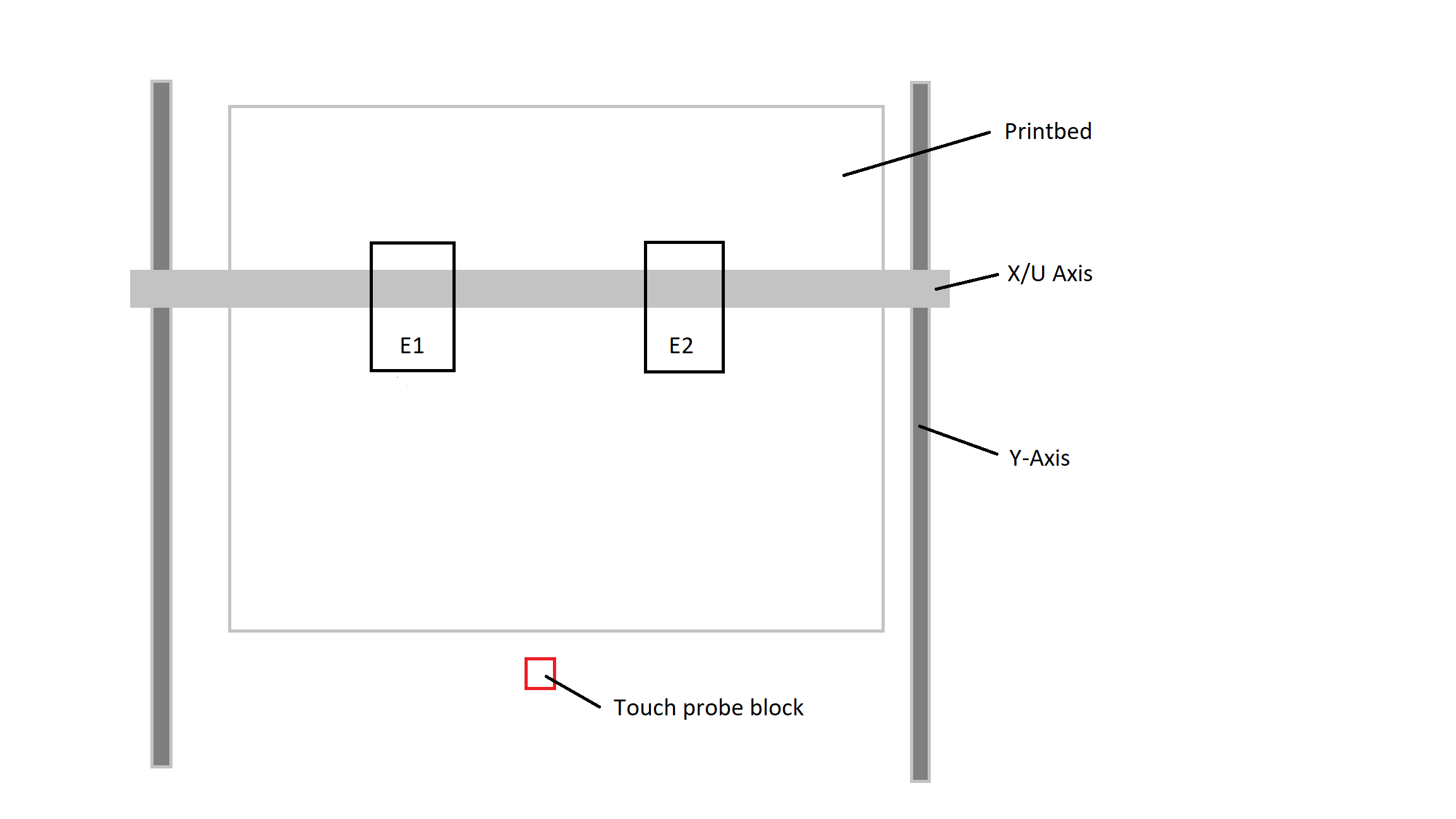
My idea is to install a nozzle probe next to printbed that can be reached by both nozzles in X and Y. In theory, the X and Y offset of each nozzle can be calculated independent of the nozzle diameter by touching the Probe with the nozzle from both sides. Right and left for X and Front and Back for Y.-
The first task is to develop a probing routine that touches the probe from both sides and calculates the exact nozzle position for one axis.
-
The second task is to calculate the nozzle offset and apply it to the tool. For normal dual nozzle setups, the offset can be stored by using the G10 command. But according to the IDEX setup manual, the nozzle offset on an IDEX Printer is set by adjusting the U axis limits, so using G10 to save the offsets won't work here I recon.

Any Ideas?
Cheers Max
-
-
-
Thank you for the link. This is a really neat system. But I would like to keep the setup as simple as possible without the need for extra hardware like an SBC+Webcam/USB-microscope. Also, the TAMV sets the offsets using the G10 command, which might not work for an IDEX printer.
-
@maxgyver FWIW I use TAMV (https://github.com/HaythamB/TAMV) on my IDEX printer. The only twist is, I need to modify the T1 offsets from being applied to X to instead U. Not too hard to do - but I did put in a feature request in Github https://github.com/HaythamB/TAMV
Example current TAMV output for T1:
G10 P1 X-0.118 Y0.237Example TAMV output for T1 w/additional axis support (IDEX, T1 on U)
G10 P1 X0 Y0.237 U-0.118Not entirely helpful as you want to avoid additional hardware (as a note, I don't run the TAMV Pi as a Duet SBC).
Not quite sure I follow your comments on G10 being used to calibrate the tools, the IDEX dozuki entry mentions using G10 a few times. I get the nozzles pretty close to 'zeroed' on the X-U axis by adjusting the M208 max/min, with the final calibration occurring in the T1 G10 line.
-
This thread is old and I assume you've solved this already...but you could also use a camera assisted solution like this: https://www.emberprototypes.com/products/cxc
Not fully automated, but a lot easier/quicker than the traditional line print patterns.