G29 command skipping grid points
-
Hi all,
I have an issue when running G29 command on my Ender 5 where I'm getting the error message: Warning : Skipping grid point ( X,Y) because Z probe cannot reach it as you can see below:
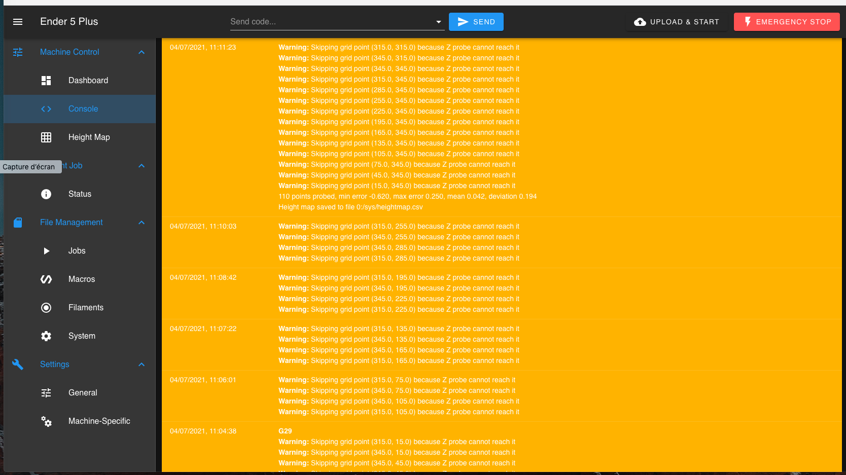
This must be an issue with my config.g and how i defined my grid and number of points to test but I cannot figure out exactly what parameter I got wrong, here's my config.g if someone can help point me to pin point the issue.
; Configuration file for Duet 3 (firmware version 3)
; executed by the firmware on start-up
;
; generated by RepRapFirmware Configuration Tool v3.1.4 on Sun Oct 04 2020 22:37:40 GMT+0200 (heure d’été d’Europe centrale); General preferences
G90 ; send absolute coordinates...
M83 ; ...but relative extruder moves
M550 P"Ender 5 Plus" ; set printer name; Network
M552 P0.0.0.0 S1 ; enable network and acquire dynamic address via DHCP
M586 P0 S1 ; enable HTTP
M586 P1 S0 ; disable FTP
M586 P2 S0 ; disable Telnet; Drives
M569 P0.0 S0 ; physical drive 0.0 goes backwards
M569 P0.1 S0 ; physical drive 0.1 goes backwards
M569 P0.2 S0 ; physical drive 0.2 goes backwards
M569 P0.4 S0 ; physical drive 0.4 goes backwards
M584 X0.0 Y0.1 Z0.2:0.3 E0.4 ; set drive mapping
M350 X16 Y16 Z16 E16 I1 ; configure microstepping with interpolation
M92 X80.00 Y80.00 Z800.00 E130.00 ; set steps per mm
M566 X900.00 Y900.00 Z12.00 E120.00 ; set maximum instantaneous speed changes (mm/min)
M203 X6000.00 Y6000.00 Z1200.00 E1200.00 ; set maximum speeds (mm/min)
M201 X500.00 Y500.00 Z20.00 E250.00 ; set accelerations (mm/s^2)
M906 X800 Y800 Z800 E800 I30 ; set motor currents (mA) and motor idle factor in per cent
M84 S30 ; Set idle timeout; Axis Limits
M208 X0 Y0 Z0 S1 ; set axis minima
M208 X350 Y350 Z400 S0 ; set axis maxima; Endstops
M574 X2 S1 P"io1.in" ; configure active-high endstop for high end on X via pin io1.in
M574 Y2 S1 P"io2.in" ; configure active-high endstop for high end on Y via pin io2.in
M574 Z2 S2 ; configure Z-probe endstop for high end on Z; Z-Probe
M950 S0 C"io4.out" ; create servo pin 0 for BLTouch
M558 P9 C"^io4.in" H5 F120 T6000 ; set Z probe type to bltouch and the dive height + speeds
G31 P500 X-42 Y-20 Z2.503 ; set Z probe trigger value, offset and trigger height
M557 X15:350 Y15:350 S30 ; define mesh grid; Heaters
M308 S0 P"temp1" Y"thermistor" T100000 B4092 ; configure sensor 0 as thermistor on pin temp1
M950 H0 C"out0" T0 ; create bed heater output on out0 and map it to sensor 0
M307 H0 B0 S1.00 ; disable bang-bang mode for the bed heater and set PWM limit
M140 H0 ; map heated bed to heater 0
M143 H0 S120 ; set temperature limit for heater 0 to 120C
M308 S1 P"temp0" Y"thermistor" T100000 B4092 ; configure sensor 1 as thermistor on pin temp0
M950 H1 C"out1" T1 ; create nozzle heater output on out1 and map it to sensor 1
M307 H1 B0 S1.00 ; disable bang-bang mode for heater and set PWM limit; Fans
M950 F0 C"out7" Q500 ; create fan 0 on pin out7 and set its frequency
M106 P0 C"Part cooling fan" S0 H1 T45 ; set fan 0 name and value. Thermostatic control is turned on
M950 F1 C"out8" Q500 ; create fan 1 on pin out8 and set its frequency
M106 P1 C"Hot-end fan" S1 H1 T45 ; set fan 1 name and value. Thermostatic control is turned on
M950 F2 C"out4" Q500 ; create fan 2 on pin out4 and set its frequency
M106 P2 C"Motherboard fan" S1 H-1 ; set fan 2 name and value. Thermostatic control is turned off
M950 F3 C"out9" Q500 ; create fan 2 on pin out4 and set its frequency
M106 P3 C"Case fan" S1 H-1 ; set fan 2 name and value. Thermostatic control is turned off; Tools
M563 P0 S"E0" D0 H1 F0 ; define tool 0
G10 P0 X0 Y0 Z0 ; set tool 0 axis offsets
G10 P0 R0 S0 ; set initial tool 0 active and standby temperatures to 0C
M563 P1 S"E1" D1 H2 F0 ; define tool 1
G10 P1 X0 Y0 Z0 ; set tool 1 axis offsets
G10 P1 R0 S0 ; set initial tool 1 active and standby temperatures to 0C; Filament runout sensor
;M581 E2 T1 S0 C1 ; Filament run-out sensor triggers a pause; Custom settings are not defined
; Miscellaneous
M575 P1 S1 B57600 ; enable support for PanelDueM501
Thanks in advance for you help
-
@aldiallo said in G29 command skipping grid points:
G31 P500 X-42 Y-20 Z2.503 ; set Z probe trigger value, offset and trigger height
M557 X15:350 Y15:350 S30 ; define mesh gridYour probe offset is -42 in x
to be able to probe X350, your nozzle needs to be at X392 (350+ the 42 offset). This is outside the maximum axis limits so its skipped.
If you want to remove those warnings, change your mesh probing to
M557 X15:300 Y15:320 -
Thank you, will give that a try.
-
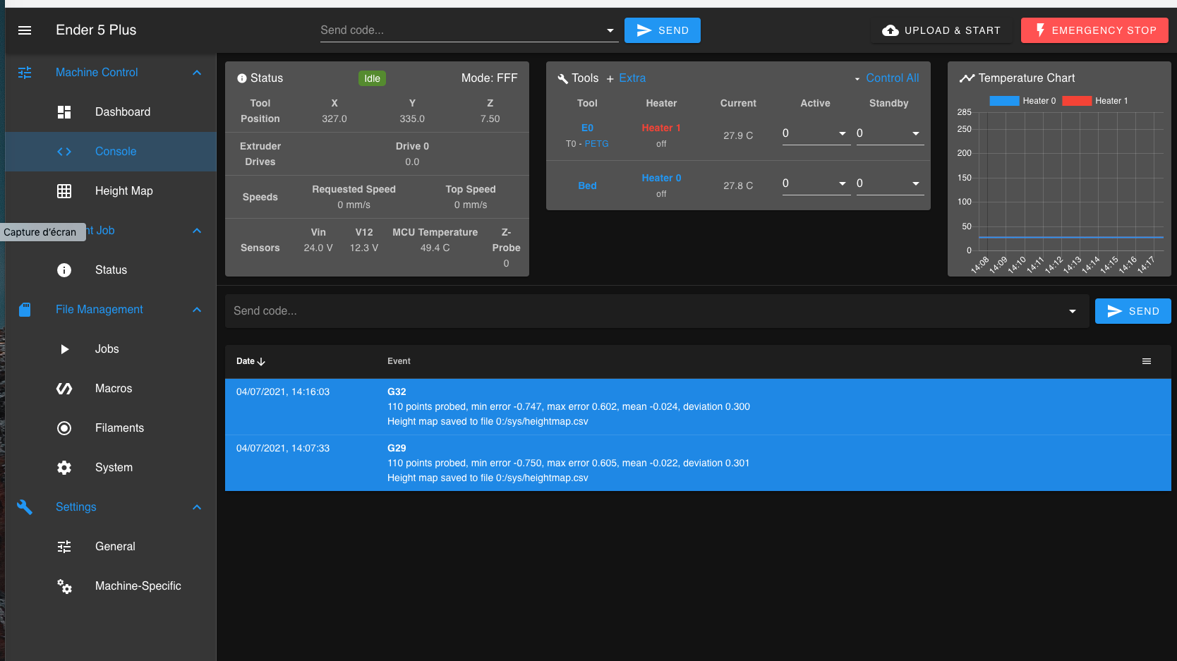
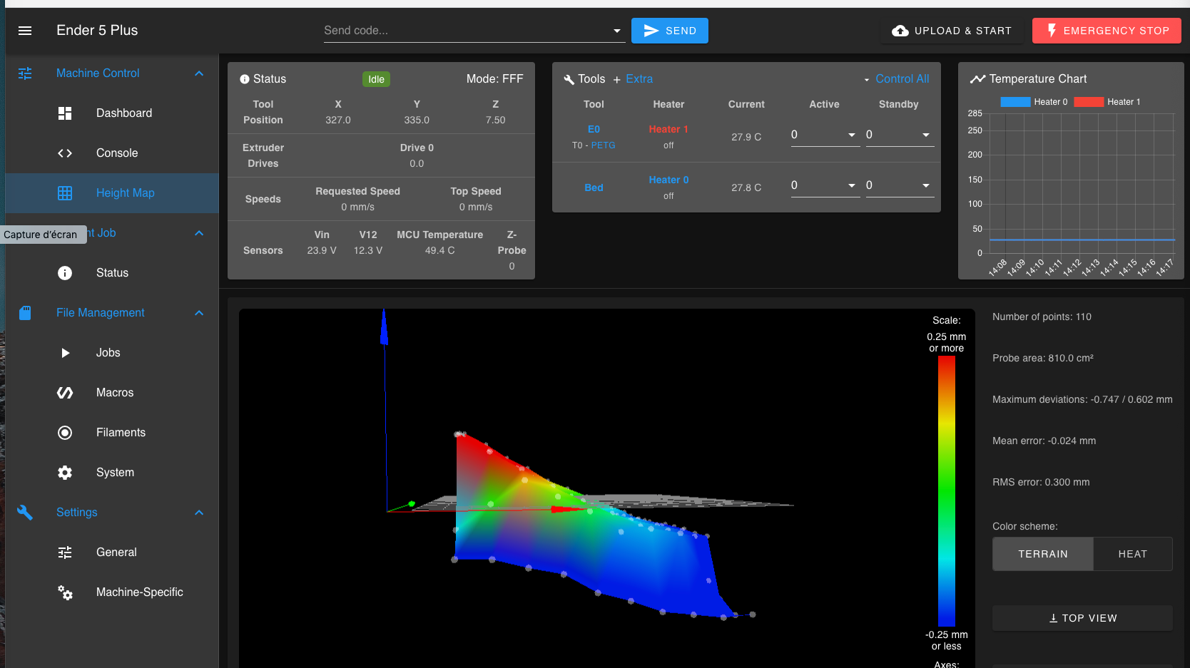
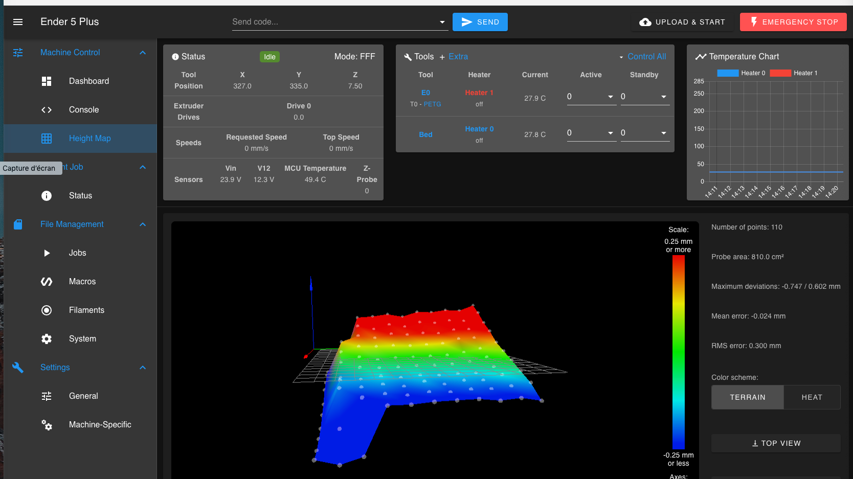
just tried it and I'm no longer getting the error but now I'm a bit concerned about the results, not sure if this is good or not:
-
Is there anything about your bed or probe mount that is different when in that area?
-
Hello,
Nothing at first sight, bed look flat to me but what I can say is that the first layer sticks better in the middle and back and also on the front right side, I'm a bit far on the left corner, so need to redo my manual bed level again. This is using the stock bltouch with the stock mount but not the stock glass bed as I replaced it with TH3D EzFlex smooth PEI and a magnetic base