Duet3D Logo Duet3D
    • Tags
    • Documentation
    • Order
    • Register
    • Login

    TC coupler stall detection. custom.how?

    Scheduled Pinned Locked Moved
    Firmware installation
    5
    19
    643
    Loading More Posts
    • Oldest to Newest
    • Newest to Oldest
    • Most Votes
    Reply
    • Reply as topic
    Log in to reply
    This topic has been deleted. Only users with topic management privileges can see it.
    • duttiundefined
      dutti
      last edited by

      hey
      I try to build my own g.code for a custom tool changer because I could´t find the sys files from E3D (website down?) .
      At the moment I need help with the stall detection of the coupler motor / homing.
      I´m not sure if I need a homec.g file ..?! Do I?
      And what should be inside?

      In general I try to copy lots of dc42 codes (convert a toolchanger....). Would be lovely If anybody could help me with that.
      R.G.

      ; Configuration file for Duet WiFi (firmware version 3)
      ; executed by the firmware on start-up
      ;
      ; generated by RepRapFirmware Configuration Tool v3.2.3 on Sat Apr 24 2021 23:46:28 GMT+0200 (Mitteleuropäische Sommerzeit)
      
      ; General preferences
      G90                                                ; send absolute coordinates...
      M83                                                ; ...but relative extruder moves
      M550 P"Z9.Hemera"                                  ; set printer name
      M669 K1                                            ; select CoreXY mode
      
      ; Network
      M552 S1                                            ; enable network
      M586 P0 S1                                         ; enable HTTP
      M586 P1 S0                                         ; disable FTP
      M586 P2 S0                                         ; disable Telnet
      
      ; Drives
      M569 P0 S1                                         ; physical drive 0 goes forwards
      M569 P1 S1                                         ; physical drive 1 goes forwards
      M569 P2 S1                                         ; physical drive 2 goes forwards
      M569 P4 S0                                         ; physical drive 3 goes forwards
      M584 X0 Y1 Z2 E4                                   ; set drive mapping
      M350 X16 Y16 Z16 E16 I1                            ; configure microstepping with interpolation
      M92 X80.00 Y80.00 Z400.00 E408.00                  ; set steps per mm
      M566 X4800.00 Y4800 Z1800.00 E1200.00              ; set maximum instantaneous speed changes (mm/min)
      M203 X12000.00 Y6000.00 Z1800.00 E6000.00          ; set maximum speeds (mm/min)
      M201 X2500.00 Y2500.00 Z1800.00 E1000.00           ; set accelerations (mm/s^2)
      M906 X1400 Y1400 Z1500 E1000 I30                   ; set motor currents (mA) and motor idle factor in per cent
      M84 S30                                            ; Set idle timeout
      
      ; Axis Limits
      M208 X0 Y0 Z0 S1                                   ; set axis minima
      M208 X300 Y300 Z300 S0                             ; set axis maxima
      
      ; Endstops
      M574 X1 S1 P"!xstop"                                ; configure active-high endstop for low end on X via pin xstop
      M574 Y1 S1 P"!ystop"                                ; configure active-high endstop for low end on Y via pin ystop
      M574 Z1 S2                                         ; configure Z-probe endstop for low end on Z
      
      ; Z-Probe
      M950 S0 C"exp.heater3"                             ; create servo pin 0 for BLTouch
      M558 P9 C"^zprobe.in" H5 F600 T6000                ; set Z probe type to bltouch and the dive height + speeds
      G31 P500 X0 Y0 Z3.3                                ; set Z probe trigger value, offset and trigger height
      M557 X10:290 Y10:290 S35                           ; define mesh grid
      
      
      ; Heaters
      M308 S0 P"bedtemp" Y"thermistor" T100000 B4138     ; configure sensor 0 as thermistor on pin bedtemp
      M950 H0 C"bedheat" T0                              ; create bed heater output on bedheat and map it to sensor 0
      M307 H0 R0.273 C481.0 D5.17 S1.00 V23.8
      M140 H0                                            ; map heated bed to heater 0
      M143 H0 S90                                        ; set temperature limit for heater 0 to 90C
      M308 S1 P"e0temp" Y"thermistor" T100000 B4138      ; configure sensor 1 as thermistor on pin e0temp
      M950 H1 C"e0heat" T1                               ; create nozzle heater output on e0heat and map it to sensor 1
      M307 H1 R1.374 C334.1 D13.35 S1.00 V24.0           ; disable bang-bang mode for heater  and set PWM limit
      M143 H1 S250                                       ; set temperature limit for heater 1 to 250C
      
      ; Fans
      M950 F0 C"fan0" Q500                               ; create fan 0 on pin fan0 and set its frequency
      M106 P0 S0 H-1                                     ; set fan 0 value. Thermostatic control is turned off
      M950 F1 C"fan1" Q500                               ; create fan 1 on pin fan1 and set its frequency
      M106 P1 S1 H1 T35                                  ; set fan 1 value. Thermostatic control is turned on
      
      
      ; Tools
      M563 P0 D0 H1 F0                                   ; define tool 0
      G10 P0 X30 Y10 Z-0.35                                    ; set tool 0 axis offsets
      G10 P0 R0 S0                                       ; set initial tool 0 active and standby temperatures to 0C
      
      ; Custom settings are not defined
      
      ; Miscellaneous
      M911 S10 R11 P"M913 X0 Y0 G91 M83 G1 Z3 E-5 F1000" ; set voltage thresholds and actions to run on power loss
      

      f0301f78-86e2-4ed0-9986-7cd6a8bf51c4-image.png

      engikeneerundefined 1 Reply Last reply Reply Quote 0
      • engikeneerundefined
        engikeneer @dutti
        last edited by

        @barbarossa-cologne it seems E3D have changed their support pages over from dozuki to zendesk
        https://e3d-online.zendesk.com/hc/en-us

        I'm sure someone here might be able to help you though 🙂

        E3D TC with D3Mini and Toolboards.
        Home-built CoreXY, Duet Wifi, Chimera direct drive, 2x BMG, 300x300x300 build volume
        i3 clone with a bunch of mods

        duttiundefined 1 Reply Last reply Reply Quote 0
        • duttiundefined
          dutti @engikeneer
          last edited by

          @engikeneer
          OK thanks a lot. I´ll try to solve as much as I can by myself.
          R.G.

          duttiundefined 1 Reply Last reply Reply Quote 0
          • duttiundefined
            dutti @dutti
            last edited by

            @barbarossa-cologne
            Would be nice if anybody can take a look over my config. Maybe it´s a small mistake of me.

            jannauundefined 1 Reply Last reply Reply Quote 0
            • jannauundefined
              jannau
              last edited by

              a homec.g file is needed. It contains the instructions to drive the C axis until the stepper drivers detect a stall. E3D's sys files are on github, see their homec.g file

              duttiundefined 1 Reply Last reply Reply Quote 0
              • duttiundefined
                dutti @jannau
                last edited by dutti

                @jannau ok thanks
                I saw it´s for rrf2. Does this matters?
                02b0d704-7f3f-49fa-bb05-01949fabdfb6-image.png

                duttiundefined 1 Reply Last reply Reply Quote 0
                • duttiundefined
                  dutti @dutti
                  last edited by

                  @barbarossa-cologne Found it for rrf3 ... sry

                  1 Reply Last reply Reply Quote 0
                  • jannauundefined
                    jannau @dutti
                    last edited by

                    @barbarossa-cologne stall detection seems to be missing for the C motor, see E3D's config.g

                    duttiundefined 1 Reply Last reply Reply Quote 0
                    • duttiundefined
                      dutti @jannau
                      last edited by

                      @jannau
                      ok it´s done. Homing is working.
                      thanks a lot
                      R.G.

                      duttiundefined dc42undefined 2 Replies Last reply Reply Quote 0
                      • duttiundefined
                        dutti @dutti
                        last edited by dutti

                        @barbarossa-cologne

                        How can I add a general offset?
                        I have defined offset for my tool (between nozzle and z switch) but I have also offset between my z switch/nozzle and the endstops (50mm) (x,y).?
                        G10 P0 X30 Y28.25 Z45 ; set tool 0 axis offsets without a P parameter?

                        And how can I allowed the printer to move outside of my axis limits to collect the tools?

                        Do I have to define the size of the bed seperately or do I do this with axis minimum and maximum?

                        Thanks
                        R.G.

                        ; Configuration file for Duet 3 (firmware version 3)
                        ; executed by the firmware on start-up
                        ;
                        ; generated by RepRapFirmware Configuration Tool v3.2.3 on Mon Aug 02 2021 16:15:35 GMT+0200 (Mitteleuropäische Sommerzeit)
                        
                        ; General preferences
                        G90                                                        ; send absolute coordinates...
                        M83                                                        ; ...but relative extruder moves
                        M550 P"Duet 3"                                             ; set printer name
                        
                        M552 S1 P192.168.2.108                                     ; Wifi
                        G4 S4
                        M574 C1 S3
                        M915 P1.2 C S0 F0 R1
                        
                        ; Drives
                        M569 P0.0 S1                                               ; physical drive 0.0 goes forwards
                        M569 P0.1 S1                                               ; physical drive 0.1 goes forwards
                        M569 P0.2 S0                                               ; physical drive 0.2 goes forwards
                        M569 P0.3 S0                                               ; physical drive 0.2 goes forwards
                        M569 P0.4 S0                                               ; physical drive 0.2 goes forwards
                        M569 P0.5 S0                                               ; physical drive 0.2 goes forwards
                        M569 P1.0 S0                                               ; physical drive 0.2 goes forwards
                        M569 P1.2 S0                                               ; physical drive 0.2 goes forwards
                        M569 P121.0 S1                                             ; physical drive 121.0 goes forwards
                        M569 P122.0 S1                                             ; physical drive 122.0 goes forwards
                        M569 P123.0 S1                                             ; physical drive 123.0 goes forwards
                        M584 X1.0 Y0.0:0.1 Z0.2:0.3:0.4:0.5 C1.2 E121.0:122.0:123.0     ; set drive mapping
                        M350 X16 Y16 Z16 E16:16:16 I1                              ; configure microstepping with interpolation
                        M92 X160.00 Y160.00 Z640.00 C91.022 E409.00:409.00:409.00          ; set steps per mm
                        M566 X900.00 Y900.00 Z60.00 C3000 E3000.00:3000.00:3000.00       ; set maximum instantaneous speed changes (mm/min)
                        M203 X12000.00 Y12000.00 Z6000.00 C5000 E6000.00:6000.00:6000.00 ; set maximum speeds (mm/min)
                        M201 X500.00 Y500.00 Z300.00 C400 E250.00:250.00:250.00         ; set accelerations (mm/s^2)
                        M906 X1300 Y1300 Z2500 C300 E1000:1000:1000 I30                 ; set motor currents (mA) and motor idle factor in per cent
                        M84 S30                                                    ; Set idle timeout
                        
                        ; Axis Limits
                        M208 X-10 Y-10 Z10 S1                                      ; set axis minima
                        M208 X850 Y850 Z850 S0                                  ; set axis maxima
                        
                        ; Endstops
                        M574 X2 S1 P"^io3.in"                                      ; configure active-high endstop for high end on X via pin ^io3.in
                        M574 Y2 S1 P"^io1.in"                                      ; configure active-high endstop for high end on Y via pin ^io1.in
                        M574 Z1 S1 P"^io2.in"                                      ; configure active-high endstop for low end on Z via pin ^io2.in
                        
                        ; Z-Probe
                        M558 P0 H-5 F300 T300                                       ; disable Z probe but set dive height, probe speed and travel speed
                        
                        M557 X10:10 Y10:10 S20                                     ; define mesh grid
                        
                        ; Heaters
                        M308 S0 P"temp0" Y"thermistor" T100000 B4138               ; configure sensor 0 as thermistor on pin temp0
                        M950 H0 C"out0" T0                                         ; create bed heater output on out0 and map it to sensor 0
                        M307 H0 B0 R0.243 C586.2 D33.87 S1.00 V0                   ; disable bang-bang mode for the bed heater and set PWM limit
                        M140 H0                                                    ; map heated bed to heater 0
                        M143 H0 S120                                               ; set temperature limit for heater 0 to 120C
                        M308 S1 P"121.temp0" Y"thermistor" T100000 B4138           ; configure sensor 1 as PT1000 on pin 121.temp0
                        M950 H1 C"out1" T1                                         ; create nozzle heater output on out1 and map it to sensor 1
                        M307 H1 B0 S1.00                                           ; disable bang-bang mode for heater  and set PWM limit
                        M143 H1 S250                                               ; set temperature limit for heater 1 to 250C
                        M308 S2 P"122.temp0" Y"pt1000" R2200                       ; configure sensor 2 as PT1000 on pin 122.temp0
                        M950 H2 C"122.out0" T2                                     ; create nozzle heater output on 122.out0 and map it to sensor 2
                        M307 H2 B0 S1.00                                           ; disable bang-bang mode for heater  and set PWM limit
                        M143 H2 S250                                               ; set temperature limit for heater 2 to 250C
                        M308 S3 P"123.temp0" Y"pt1000" R2200                       ; configure sensor 3 as PT1000 on pin 123.temp0
                        M950 H3 C"123.out0" T3                                     ; create nozzle heater output on 123.out0 and map it to sensor 3
                        M307 H3 B0 S1.00                                           ; disable bang-bang mode for heater  and set PWM limit
                        M143 H3 S250                                               ; set temperature limit for heater 3 to 250C
                        
                        ; Fans
                        M950 F0 C"121.out1" Q500                                   ; create fan 0 on pin 121.out1 and set its frequency
                        M106 P0 S0 H-1                                             ; set fan 0 value. Thermostatic control is turned off
                        M950 F1 C"121.out2" Q500                                   ; create fan 1 on pin 121.out2 and set its frequency
                        M106 P1 S1 H1 T45                                          ; set fan 1 value. Thermostatic control is turned on
                        M950 F2 C"122.out1" Q500                                   ; create fan 2 on pin 122.out1 and set its frequency
                        M106 P2 S1 H-1                                             ; set fan 2 value. Thermostatic control is turned off
                        M950 F3 C"122.out2" Q500                                   ; create fan 3 on pin 122.out2 and set its frequency
                        M106 P3 S1 H2 T45                                          ; set fan 3 value. Thermostatic control is turned on
                        M950 F4 C"123.out1" Q500                                   ; create fan 4 on pin 123.out1 and set its frequency
                        M106 P4 S1 H-1                                             ; set fan 4 value. Thermostatic control is turned off
                        M950 F5 C"123.out2" Q500                                   ; create fan 5 on pin 123.out2 and set its frequency
                        M106 P5 S1 H3 T45                                          ; set fan 5 value. Thermostatic control is turned on
                        M950 F6 C"out4" Q500                                       ; create fan 6 on pin out4 and set its frequency
                        M106 P6 S1 H-1                                             ; set fan 6 value. Thermostatic control is turned off
                        M950 F7 C"out5" Q500                                       ; create fan 7 on pin out5 and set its frequency
                        M106 P7 S1 H T45                                           ; set fan 7 value. Thermostatic control is turned on
                        
                        ; Tools
                        M563 P0 D0 H1 F0                                           ; define tool 0
                        G10 P0 X30 Y28.25 Z45                                      ; set tool 0 axis offsets
                        G10 P0 R0 S0                                               ; set initial tool 0 active and standby temperatures to 0C
                        M563 P1 D1 H2 F2                                           ; define tool 1
                        G10 P1 X0 Y0 Z0                                            ; set tool 1 axis offsets
                        G10 P1 R0 S0                                               ; set initial tool 1 active and standby temperatures to 0C
                        M563 P2 D2 H3 F4                                           ; define tool 2
                        G10 P2 X0 Y0 Z0                                            ; set tool 2 axis offsets
                        G10 P2 R0 S0                                               ; set initial tool 2 active and standby temperatures to 0C
                        
                        ; Custom settings are not defined
                        
                        ; Miscellaneous
                        M911 S10 R11 P"M913 X0 Y0 G91 M83 G1 Z3 E-5 F1000"         ; set voltage thresholds and actions to run on power loss
                        

                        @jannau

                        duttiundefined Phaedruxundefined 2 Replies Last reply Reply Quote 0
                        • duttiundefined
                          dutti @dutti
                          last edited by

                          This post is deleted!
                          1 Reply Last reply Reply Quote 0
                          • dc42undefined
                            dc42 administrators @dutti
                            last edited by

                            @barbarossa-cologne, I tried to get stall detection working for the coupler motor. Unfortunately that motor gets quite hot during use, so stall detection parameters that work when the motor is cold don't work when it is hot.

                            Duet WiFi hardware designer and firmware engineer
                            Please do not ask me for Duet support via PM or email, use the forum
                            http://www.escher3d.com, https://miscsolutions.wordpress.com

                            duttiundefined 2 Replies Last reply Reply Quote 0
                            • duttiundefined
                              dutti @dc42
                              last edited by

                              @dc42 ok but that's not a problem in my case ?
                              Should I use different ways to home coupler?
                              Thanks
                              R.G.

                              1 Reply Last reply Reply Quote 0
                              • duttiundefined
                                dutti @dc42
                                last edited by

                                @dc42
                                I just wanna know about the offsets x and y. Coupler is working fine. Thanks a lot
                                R.G.

                                1 Reply Last reply Reply Quote 0
                                • Phaedruxundefined
                                  Phaedrux Moderator @dutti
                                  last edited by

                                  @barbarossa-cologne said in TC coupler stall detection. custom.how?:

                                  And how can I allowed the printer to move outside of my axis limits to collect the tools?
                                  Do I have to define the size of the bed seperately or do I do this with axis minimum and maximum?

                                  If the print head can leave the printable area to pick up the tool you can either change the M208 limits such that the minima goes into the negative enough to allow for the full true range of motion while keeping the 0,0 point on the printable area. Or if it's on the positive side you could extend the maximum range temporarily. Or even just allow movement outside of the bounds temporarily.

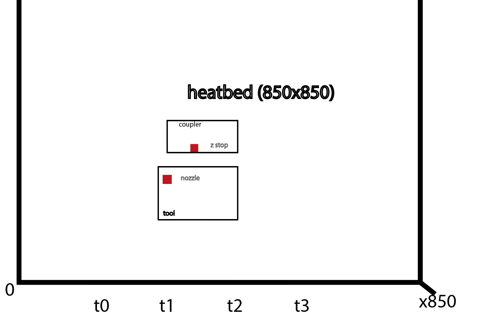
                                  Can you show us a diagram illustrating your offsets?

                                  Z-Bot CoreXY Build | Thingiverse Profile

                                  duttiundefined 3 Replies Last reply Reply Quote 0
                                  • duttiundefined
                                    dutti @Phaedrux
                                    last edited by

                                    @phaedrux

                                    22a39019-3195-4f34-abf4-e4ca22c28720-image.png

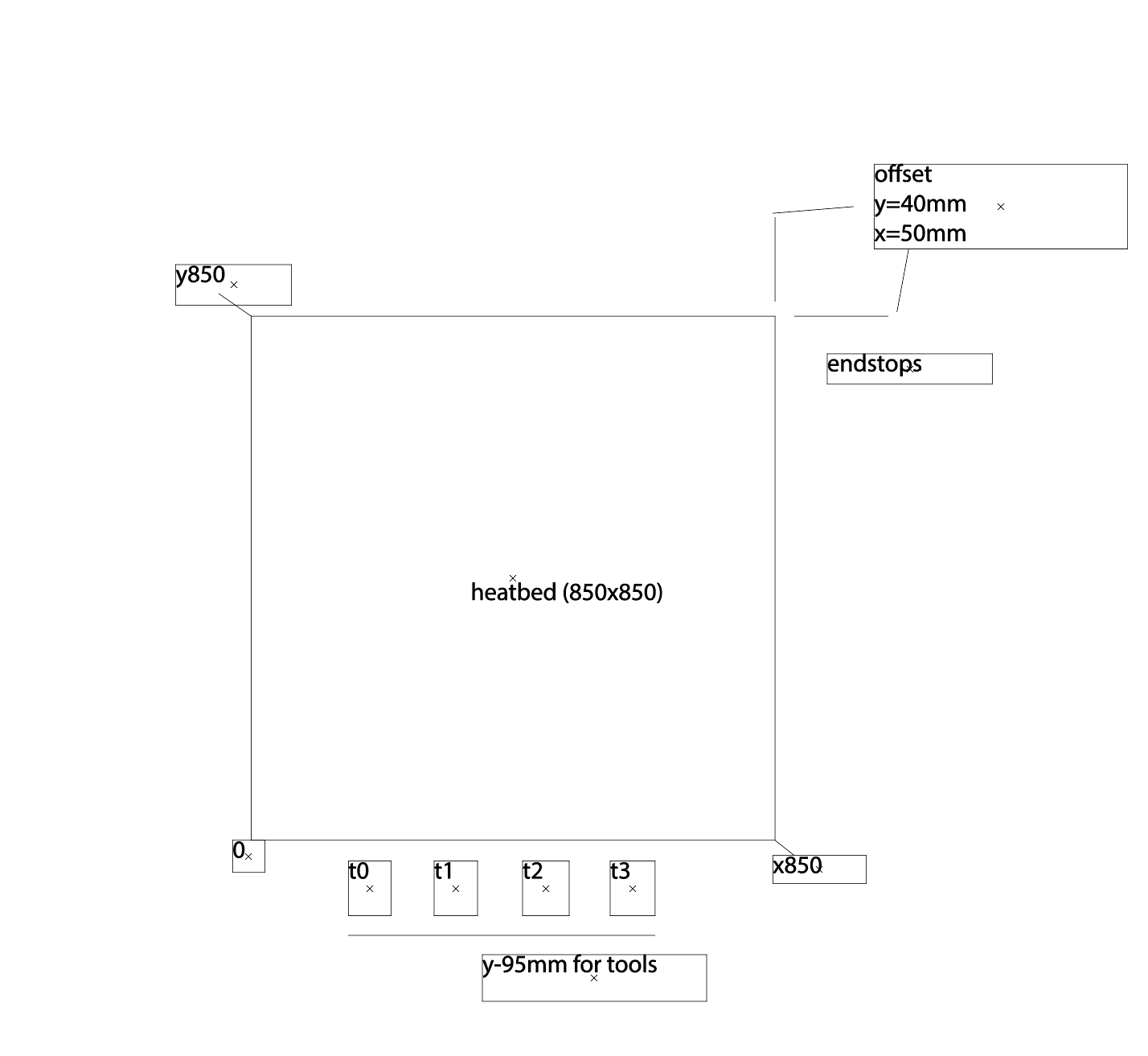
                                    I hope that is understandable...
                                    that´s the last thing ( I hope) before start printing first time. thank you guys

                                    1 Reply Last reply Reply Quote 0
                                    • duttiundefined
                                      dutti @Phaedrux
                                      last edited by

                                      @phaedrux

                                      ; Tools
                                      M563 P0 D0 H1 F0 ; define tool 0
                                      G10 P0 X30 Y28.25 Z45 ; set tool 0 axis offsets

                                      this iy my tool offfset.
                                      tool is in front of coupler (nearer to y0). So is it rigth to have a positiv number for the offset)?
                                      Example; IN REAL. when x axis switch it at x100/y100 the nozzle is at x70/y71.75.
                                      Thank you
                                      R.G.

                                      1 Reply Last reply Reply Quote 0
                                      • duttiundefined
                                        dutti @Phaedrux
                                        last edited by

                                        @phaedrux 50234d55-1dfd-46e2-8cfa-bad9022187a5-image.png

                                        duttiundefined 1 Reply Last reply Reply Quote 0
                                        • duttiundefined
                                          dutti @dutti
                                          last edited by

                                          @barbarossa-cologne

                                          Problem solved!

                                          1 Reply Last reply Reply Quote 0
                                          • First post
                                            Last post
                                          Unless otherwise noted, all forum content is licensed under CC-BY-SA