Duet 6HC and 3HC Expansion board CAN connection not working
-
Hi there,
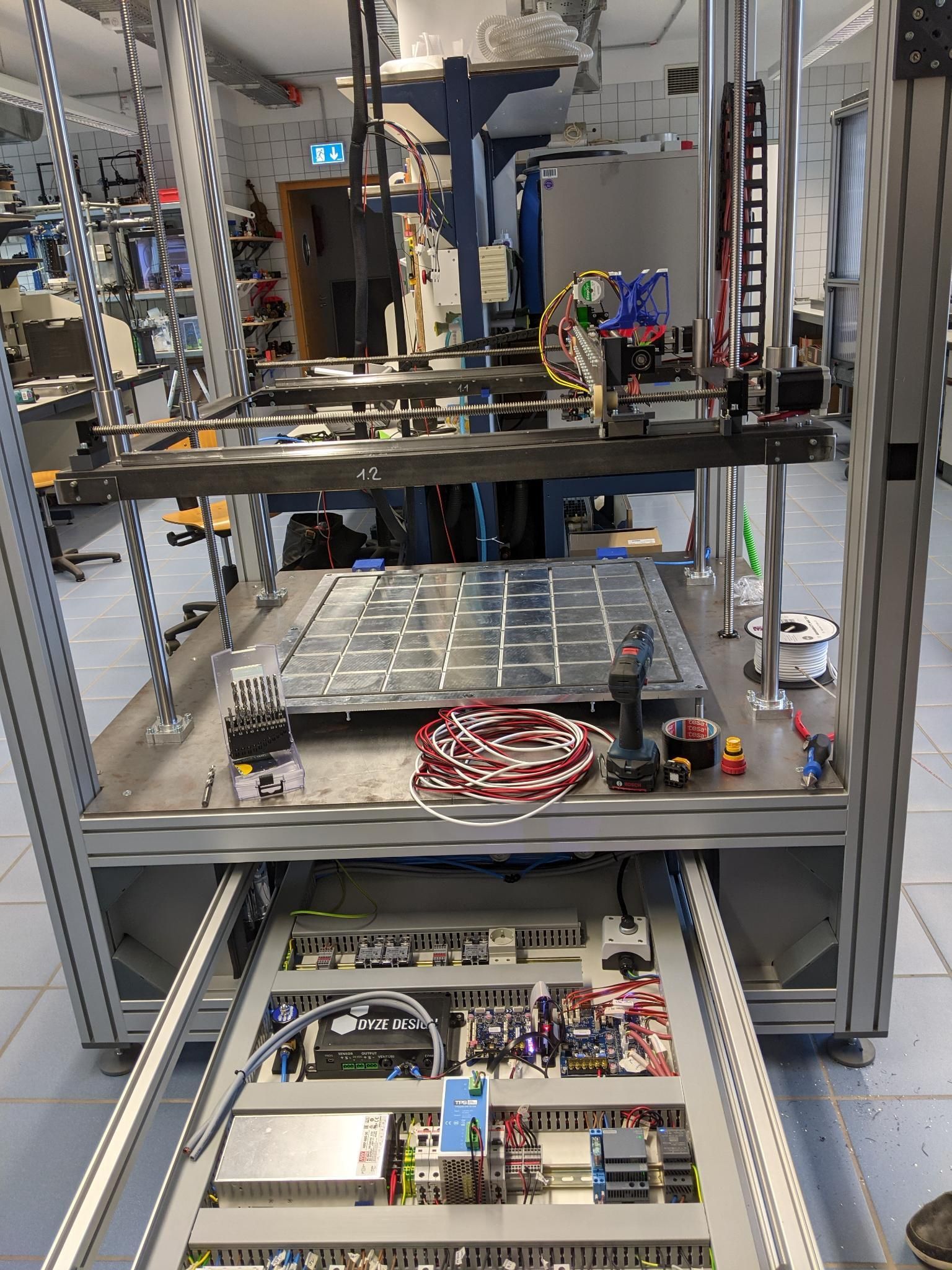
we're currently in the process of building a big printer with a pulsar pellet extruder.

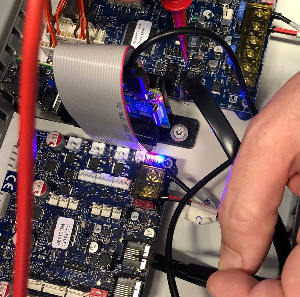
The main board is a Duet3 6HC which is working great so far but now we need the 3HC Expansion to drive the Pulsar. We connected both via RJ11 but there is no reaction from the red Status LED everyone is talking about, no matter if the DIP switches are all off or not


Michael
-
@visnu777 Have you set the termination jumpers correctly? You also need to set the address. If this is the first and only expansion board, the you should have dip switch1 on, and the rest off. https://duet3d.dozuki.com/Wiki/CAN_connection
Edit - This might useful too https://d17kynu4zpq5hy.cloudfront.net/igi/duet3d/E3tTcEmkPScIAR1V.huge
-
@deckingman Thanks for your reply
 It should be terminated correctly, as I understood it both jumpers should be closed on the last device on the bus (see the picture I posted)
The DIp switch was originally in 1000 position but it was the same result., no blinking status led. According to the documentation it should work with all off too
-
@visnu777 said in Duet 6HC and 3HC Expansion board CAN connection not working:
.................. According to the documentation it should work with all off too
According to the documentation that I've read, if all 4 switches are in the off position, the board will factory reset and request firmware from the main board.
https://duet3d.dozuki.com/Wiki/CAN_connection#Section_Factory_resetting_a_tool_or_expansion_board
-
So you might want to re-instal the firmware on the expansion board. Extract from the docs.......
..............Ensure that the correct expansion board firmware binary (for example, Duet3Firmware-EXP3HC.bin for the 3-driver high current expansion board) is present in the /sys folder (on the RPi if using it, or on the SD card if running standalone)
...............set the expansion board address to zero (switches all off) and press the Reset button on the expansion board to commence the firmware update (or power down, change the switches, and power up again). When re-syncing is complete, change the switches back to the correct board address and press Reset again (or power down, change the switches, and power up again).
You can check the firmware version installed on an expansion board by sending M115 B# where has is the board number.EDIT. If that doesn't work - you might need to update the boot loader - instructions to do that are here https://duet3d.dozuki.com/Wiki/Updating_the_bootloader_on_Duet_3_expansion_and_tool_boards
-
@deckingman Thanks, will try that tomorrow but the LED should do something regardless of the address? I already tried the manual firmware flash by gcode from the DWC. We also tried the 1000 first but the CAN led between the two RJ11 ports never showed any sign of life yet

-
Is the cable definitely the correct type? Do you have another to test with?
-
@phaedrux Its a custom RJ11 6pin cable with successful continuity check.
edit: We already tried another one, check made with the cable plugged in on the exposed pins on board. -
@phaedrux
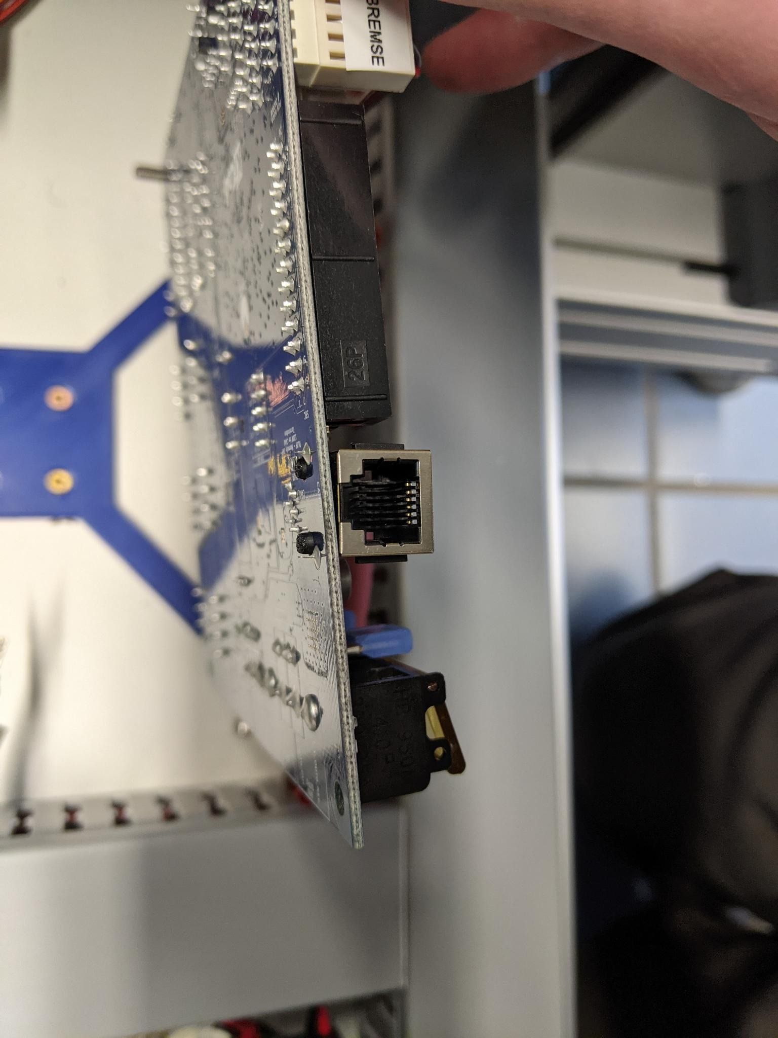
I just checked the cable for continuity again (works) and additionally I checked it on the exposed pins of the rj11 conenctor on the board (see picture)
Strange thing (or not, might be normal): When I check it like on the picture (left CAN pin), both CAN pins in the middle give me a beep on Mainboard side, is that normal? When the right pin on the EXP is tested only the right pin beeps

Pressing reset (with FW file in the right folder and all DIP off) does nothing, setting dip adress on 1 also.
Any clues? It never worked, never had connected anything else but the CAN cables and power supply and the diagnostic LED never showed any falshing or steady red light. Is the board DOA?
-
@visnu777 said in Duet 6HC and 3HC Expansion board CAN connection not working:
Strange thing (or not, might be normal): When I check it like on the picture (left CAN pin), both CAN pins in the middle give me a beep on Mainboard side, is that normal? When the right pin on the EXP is tested only the right pin beeps
If I'm understanding you correctly:
You cannot possibly have different continuity from one connector vs. the other with everything connected and a good cable.If everything is right, the ends must give equal results, or the end to end connections do not exist.
It could be a bad crimp at one end, with something open or possibly two cores under one contact??
Also check for a "sprained" contact wire in either connector? I have know one get twisted so it does not properly sit in the contact groove in the plug.
Out of line contacts are also again possible in conjunction with a bad plug crimp, eg. with a generic or mismatched tool [there is no single standard between makers], so the plug contact inserts are not fully seated below the level of the plug surface - the socket wires can drop between the plug contact inserts rather than lining up with each one, causing random mis-connects.
-
@rjenkinsgb
I think I found another clue and it looks like it has nothing to do with the EXP HC3:Without CAN connection a continuity test between the two CAN pins on the Mainboard beeps when the board is powered otherwise not. So something on board switches the two together when we have power. Is it possible to do that via firmware?
I told the students building the printer to do a check with an empty config to rule that out...edit: I also checked the connectors, the one on the HC6 lokks ok connectorwise but is not well soldered at all, didnt notice before


edit: New clue: Empty Config makes it go away (with hard reset) but CAN indicator led still does nothing,
old firmware makes the weird thing come back. -
I've asked @DC42 to take a look and give his thoughts.
-
@visnu777 sorry for the delay, I have been out for the past two days. A few questions for you:
- Is the green 3.3V LED on the 3HC board lit?
- Is anything connected to the 3HC apart from power and CAN, e.g. endstop switches? If so, please disconnect them and try again.
- Does the red LED between the CAN connectors on the 3HC light up at all?
The mounting of the 6HC CAN connector definitely isn't right. It looks like one of the plastic pegs of the connector wasn't pushed far enough into the PCB when the connector was fitted. However, it does appear that all 6 pins of the connector protrude from the underside of the PCB, so they should be making good contact. The board is tested using pogo pins that make contact with those pins.
Regarding continuity, with power off, CAN cable connected and the termination jumpers removed from the 3HC, you should get 120 ohms between the two outer termination pins. With the jumpers fitted you should get 60 ohms between the two jumpers.
-
Hi dc42

@dc42 said in Duet 6HC and 3HC Expansion board CAN connection not working:
Is the green 3.3V LED on the 3HC board lit?
All LEDs are lit.
@dc42 said in Duet 6HC and 3HC Expansion board CAN connection not working:
Is anything connected to the 3HC apart from power and CAN, e.g. endstop switches? If so, please disconnect them and try again.
no, nothing connected but CAN and power
Regarding continuity, with power off, CAN cable connected and the termination jumpers removed from the 3HC, you should get 120 ohms between the two outer termination pins. With the jumpers fitted you should get 60 ohms between the two jumpers.@dc42 said in Duet 6HC and 3HC Expansion board CAN connection not working:
Does the red LED between the CAN connectors on the 3HC light up at all?
No. Never did according to the builders

@dc42 said in Duet 6HC and 3HC Expansion board CAN connection not working:
Regarding continuity, with power off, CAN cable connected and the termination Regarding continuity, with power off, CAN cable connected and the termination jumpers removed from the 3HC, you should get 120 ohms between the two outer termination pins. With the jumpers fitted you should get 60 ohms between the two jumpers.jumpers removed from the 3HC, you should get 120 ohms between the two outer termination pins. With the jumpers fitted you should get 60 ohms between the two jumpers.
I'll check next week, its at university/work
 Thanks for your advice
-
@dc42 said in Duet 6HC and 3HC Expansion board CAN connection not working:
Regarding continuity, with power off, CAN cable connected and the termination jumpers removed from the 3HC, you should get 120 ohms between the two outer termination pins. With the jumpers fitted you should get 60 ohms between the two jumpers.
The 3hc has the right resistance

-
@visnu777 if you connect only power to the 3HC an set the dip switches to all "0" then power cycle the board does the red LED between the can connectors light up?
-
@t3p3tony
no, it was never light up so far. -
@visnu777 thanks can you contact warranty@duet3d.com referencing this thread.
-
@t3p3tony
For the mainboard or the expansion? After all this troubleshooting I'm somewhat sure that its the HC6s CAN fault but I have no spare to test if the HC3 works... -
@visnu777 if the LED is not flashing on the expansion board then it either has a fault or has lost its bootloader (which needs a Atmel ICE to reprogram). The might be an issue with the mainboard CAN as well but that's not possible to diagnose further without a working CAN-FD expansion board.