Mesh problem after G32
-
Config file:
; Configuration file for Duet WiFi (firmware version 3)
; executed by the firmware on start-up
;
; generated by RepRapFirmware Configuration Tool v3.2.3 on Mon Jun 14 2021 12:17:56 GMT+0200 (hora de verano de Europa central)
;M929 P"eventlog.txt" S1							; Guarda un log de lo que pasa con la placa eventlog.txt

; General preferences
G90												; send absolute coordinates...
M83												; ...but relative extruder moves
M550 P"HBot XL RRF3"						    ; set printer name
M669 K1											; select CoreXY mode

; Network

M552 S1											; enable network
M586 P0 S1										; enable HTTP
M586 P1 S1										; enable FTP
M586 P2 S0										; enable Telnet

; Drives
M569 P0 S1										; X physical drive 0 goes forwards
M569 P1 S0										; Y physical drive 1 goes backwards
M569 P2 S1										; Z1 physical drive 2 goes forwards
M569 P3 S0										; E0 physical drive 3 goes backwards
M569 P4 S1										; Z2 physical drive 3 goes backwards
M584 X0 Y1 Z2:4 E3								; set drive mapping
M350 X16 Y16 Z16 E16 I1							; configure microstepping with interpolation
M92 X80.00 Y80.00 Z400.00 E400.00				; set steps per mm
M566 X500.00 Y500.00 Z60.00 E600.00				; set maximum instantaneous speed changes (mm/min)
M566 P1
M203 X18000.00 Y18000.00 Z800.00 E4800.00		; set maximum speeds (mm/min)
M201 X2000.00 Y2000.00 Z400.00 E4000.00			; set accelerations (mm/s^2)
M204 P1200.0 T5000.0                                     ; set print and travel accelerations (mm(s^2)
M566 E400						;300	  ; Set maximum instantaneous speed changes (JERKS) (mm/min) ONLY EXTRUDER
M205 X8 Y8 Z8							; Set maximum instantaneous speed changes (JERKS) (mm/seg) XYZ . USE this for Marlin COMPATIBILITY
M906 X1000 Y1000 Z1000 E560 I30					; set motor currents (mA) and motor idle factor in per cent
M84 S30											; Set idle timeout

; Axis Limits
M208 X0 Y0 Z-1 S1								; set axis minima
M208 X330 Y325 Z400 S0							; set axis maxima

; Definimos Leadscrews para el Z_Tilt
M671 X-59.13:437.87 Y164:164 S5			        ; leadscrews at left (connected to Z) and right (connected to E1) of X axis ---	S Ajustarlo segun sensibilidad del probe

; Endstops
M574 X1 S1 P"!xstop"							; configure active-low endstop for low end on X via pin xstop
M574 Y2 S1 P"!ystop"							; configure active-low endstop for high end on Y via pin ystop
;574 Z1 S0										; no need, So not used anymore

; Filament Sensor
M98 P"0:/sys/00-Functions/FilamentsensorStatus"

; Z-Probe
M558 P8 C"zprobe.in" H3 F120:80 T9000 R0.4 A3 S0.03 ;B1             ; Set Z probe type mini ir sensor
G31 P500 X18 Y-38 Z2.175					    ; set Z probe trigger value, offset and trigger height
;M557 X18:310 Y15:285 P6						; define mesh grid P6 hace 6 malla de 6x6
M557 X18:310 Y15:285 P3						; define mesh grid P6 hace 3 malla de 3x3

; Heaters BED
M308 S0 P"bedtemp" Y"thermistor" T100000 B3950 A"Heated Bed"	; configure sensor 0 as thermistor on pin bedtemp
M950 H0 C"bedheat" T0							; create bed heater output on bedheat and map it to sensor 0
M307 H0 B0 S1.00								; disable bang-bang mode for the bed heater and set PWM limit
M140 H0											; map heated bed to heater 0
M143 H0 S120									; set temperature limit for heater 0 to 120C
M143 H0 P0 S120 A2								; disable temporarily H0 if temp exceeds 120C
M143 H0 P0 S130 A0								; heater fault H0 if temp exceeds 130C
M570 H0 P60 T15 S0

; Heaters HOTEND
M308 S1 P"e0temp" Y"thermistor" T100000 B4725 C7.06e-8 A"Nozzle T0" ; Configure sensor 1 as thermistor on pin e0temp
M950 H1 C"e0heat" T1									; create nozzle heater output on e0heat and map it to sensor 1
M307 H1 B0 S1.00										; disable bang-bang mode for heater	and set PWM limit
M143 H1 S290											; set temperature limit for heater 1 to 300C
M143 H1 S275 A2											; disable temporarily H1 if temp exceeds 275C
M143 H1 S285 A0											; heater fault H1 if temp exceeds 280C
M570 H1 P10 T30 S0										; heater fault for 10 seg of 30ยบC excursion

;PID backup
M307 H0 R0.322 C632.982:632.982 D5.13 S1.00 V24.3 B0 I0		; Bed PID
M307 H1 R2.813 C295.614:204.933 D6.24 S1.00 V24.5 B0 I0		; Hotend PID

; Fan0 = Part Coooling
M950 F0 C"fan0" Q500							; create fan 0 on pin fan0 and set its frequency
M106 P0 C"LayerFAN" S0 H-1 B0.3					; set fan 0 name and value. Thermostatic control is turned off

; Fan1 = Hotend
M950 F1 C"fan1" Q500							; create fan 1 on pin fan1 and set its frequency
M106 P1 C"ToolFAN" S1 H1 T60					; set fan 1 name and value. Thermostatic control is turned on

; Fan2 = Chamber cam
M950 F2 C"fan2" Q500							; create fan 2 on pin fan2 and set its frequency
M106 P2 I0 C"ChamFAN" S0 H-1                    ; Set fan 2 PWR fan

; Sensor = MotherBoard Cooling
;----MCU & DRIVERS sensors------
;M912 P0 S-13							        ; Cpu temp correction MUST BE ADJUSTED ON EACH BOARD
M308 S3 Y"mcu-temp"	A"MCU"						; create sensor for MCU temp M308 S3 Y"mcutemp"
M308 S4 Y"drivers"	A"Drivers"					; create sensor for drivers temp M308 S4 Y"drivers"

; Tools
M200 D1.75
M563 P0 S"T0" D0 H1 F0							; define tool 0
G10 P0 X0 Y0 Z0									; set tool 0 axis offsets
G10 P0 R0 S0									; set initial tool 0 active and standby temperatures to 0C
M302 S180 R180                                         ; allow extrusion starting from 180°C and retractions already from 180°C

; Firmware Retraction
M404 N1.75										; Define filament diameter for print monitor
M207 S0.95 R0 F2400 Z0							; Firmware retraction

; Bed Compensation Taper
M376 H10										; Bed Compensation Taper 10mm

; Pressure Advance
;M572 D0 S0.09			;PLA
;M572 D0 S0.11			;PETG
;M572 D0 S0.1			;ABS

; LCD
M575 P1 S1 B57600								; enable support for PanelDue

; LEDS
M950 P1 C"e1heat" Q500							;use heater 1 outupt for LED
M42 P1 S1										; turn on LEDS


; Power Management
M911 S22.5 R24 P"M913 X0 Y0 G91 M83 G1 Z3 E-5 F1000"		; set voltage thresholds and actions to run on power loss
; Selecto Tool 0
T0												; select first tool
; Load config-override
M501											; load saved parameters from non-volatile memory
; Load Preloaded filamento config
M703
bed.g
; bed.g
; called to perform automatic bed compensation via G32
; Centro CON offset probe para los G1: 146,198
; Centro SIN offset probe para los G30:164,160
; generated by RepRapFirmware Configuration Tool v3.2.3 on Mon Jun 14 2021 12:17:56 GMT+0200 (hora de verano de Europa central)
;
; Variables
var midX=((move.axes[0].max-move.axes[0].min)/2)-sensors.probes[0].offsets[0])
var midY=((move.axes[1].max-move.axes[1].min)/2)-sensors.probes[0].offsets[1])
var midXP=((move.axes[0].max-move.axes[0].min)/2))
var midYP=((move.axes[1].max-move.axes[1].min)/2))
var tiltZ1=(move.axes[0].min+sensors.probes[0].offsets[0])
var tiltZ2=(move.axes[0].max-sensors.probes[0].offsets[0])

;
M291 P"Probing Z-tilt process started" R"Probing.." S1 T2
M561                                                   ; clear any existing bed transform
if !move.axes[0].homed || !move.axes[1].homed || !move.axes[2].homed
        G28                                            ; home all axis without mesh bed level
M558 F120:80 H3 A5 S0.01 ;                   ; Slow z-probe, up to 5 probes until disparity is 0.02 or less - else yield average.
while iterations <=2                                   ; perform 3 passes
   G30 P0 X{var.tiltZ1} Y{var.midYP} Z-99999                               ; probe near a leadscrew, half way along Y axis
   G30 P1 X{var.tiltZ2} Y{var.midYP} Z-99999 S2                           ; probe near a leadscrew and calibrate 2 motors
   G1 X{var.midX} F10000                                      ; move to the center of the bed
   G30                                                 ; probe the bed at the current xy position
   M400

   ; finish all moves, clear the buffer
;
M558 H5 F120:80 T9000 R0.4 A3 S0.03                              ; IR sensor
;
echo "Gantry deviation of " ^ move.calibration.initial.deviation ^ "mm obtained."
;
G1 Z8                                                  ; raise nozzle 8mm to ensure it is above the z probe trigger height
homeall.g
; =========================================================================================================
;
; Home xyz Axis
;
; for H-Bot XL by Campy3d
;
; =========================================================================================================
;
; Variables
var midX=((move.axes[0].max-move.axes[0].min)/2)-sensors.probes[0].offsets[0])
var midY=((move.axes[1].max-move.axes[1].min)/2)-sensors.probes[0].offsets[1])
;

G91                                                    ; relative positioning
G1 H2 X0.5 F10000                                      ; energise motors to ensure they are not stalled
M400                                                   ; wait for current moves to finish
G4 P200                                                ; wait 200ms
;
G1 H2 Z5 F6000                                         ; lift Z relative to current position
M400                                                   ; wait for current moves to finish
;
; =========================================================================================================
; Home X Axis
; =========================================================================================================
;
G1 H1 X5 F1000						  					; move slowly away
G1 H1 X-400 F3000 										; move quickly to X axis endstop and stop there (first pass)
G1 X10 F6000       										; go back a few mm
G1 H1 X-400 F360  										; move slowly to X axis endstop once more (second pass)
G1 X10 F6000												; go back a few mm
M400														; wait for current moves to finish
G4 P200                                                		; wait 200ms
;
; =========================================================================================================
; Home Y Axis
; =========================================================================================================
;
G1 H1 Y-5 F1000						  						; move slowly away
G1 H1 Y400 F3000 											; move quickly to Y axis endstop and stop there (first pass)
G1 Y-10 F6000       											; go back a few mm
G1 H1 Y400 F360  											; move slowly to Y axis endstop once more (second pass)
G1 Y-10 F6000													; go back a few mm
M400														; wait for current moves to finish
G4 P200                                                		; wait 200ms
;
G90                                                    		; absolute positioning
;
; =========================================================================================================
; Home Z Axis
; =========================================================================================================
;
;G1 X146 Y198 F6000 											; go to first probe point
G1 X{var.midX} Y{var.midY} F6000
G30               											; home Z by probing the bed
M400                                              		    ; wait for current moves to finish
;G1 Z1.15 F360                                       	    ; move z to origin and 1.15mm above bed
;M400                                                   		; wait for current moves to finish
; =========================================================================================================
; HOMED
; =========================================================================================================
If I run
G28
G32
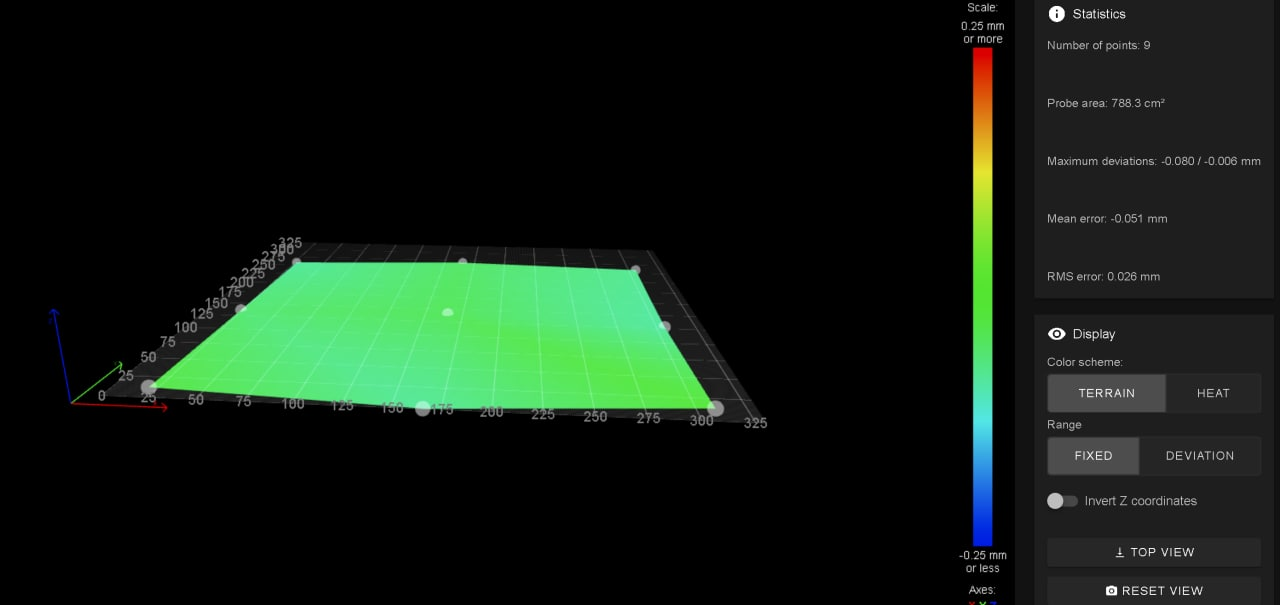
G29I´ve got this

Move the bed springs to correct the bed. and got this

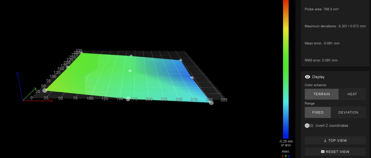
Run a G32 back again and I get again the bed tilting to the right like this

What am I missing?
-
Do you have the leadscrew locations (the M671 line ) swapped in relation to the two Z drives?
That would magnify errors rather than correcting them, I believe?
-
@rjenkinsgb The lead screws are fine, and Z map to the correct one. If I swap the Z drive mapping, the slope goes and gopes to the other way...
Only thing I did not do by the wiki, is the mini IR config.
It´s a duet2 with and rater than P1 I used P8 like with a duet3.
Could that be?
-
@apak I change the config to P1 (mini IR probe) and did
G28
G32
G29adjusted the leveling screws and got this
Powerd off and back on
G28
G32
G29
and got this
-
I think it has to be with the light and refraction on bed surface......
-
As a troubleshooting step for the IR probe, cover your bed in a sheet of plain paper to cut any reflections etc.
-
@phaedrux It´s covered by a printed part. It has to do with false reading, due to surface not even on different reading points.
First print with hairspray over the pei surface did fine.
Second print, reading over a area with printed footprint withou hairspray trigger at different height, that´s why it happen.....
-
I had so many problems with IR sensors I gave up on them.
I have printers with BLTouch devices, inductive sensing devices and one with the Euclid micro-switch device. So far the Euclid outperforms the others but it was the most trouble to retrofit to my printer. For I new design I would use the Euclid.
Frederick