The height map is not created correctly
-
@droftarts thank you for your reply.
I'm on my way home from school, so I'll post it when I get there. -
@droftarts said in The height map is not created correctly:
config.g
Thank you for your patience.
Here is my config.g.; Configuration file for Duet WiFi (firmware version 3.3) ; executed by the firmware on start-up ; ; generated by RepRapFirmware Configuration Tool v3.3.5 on Fri Nov 05 2021 01:14:08 GMT+0900 (日本標準時) ; General preferences M575 P1 S1 B57600 ; enable support for PanelDue G90 ; send absolute coordinates... M83 ; ...but relative extruder moves M550 P"kotuo02" ; set printer name ; Network M551 P"kotuo" ; set password M552 S1 ; enable network M586 P0 S1 ; enable HTTP M586 P1 S0 ; disable FTP M586 P2 S0 ; disable Telnet ; Drives M569 P0 S1 ; physical drive 0 goes forwards M569 P1 S1 ; physical drive 1 goes backwards M569 P2 S0 ; physical drive 2 goes backwards M569 P3 S1 ; physical drive 3 goes forwards M584 X0 Y1 Z2 E3 ; set drive mapping M350 X16 Y16 Z16 E16 I1 ; configure microstepping with interpolation M92 X80.00 Y80.00 Z4000.00 E369.00 ; set steps per mm M566 X600.00 Y600.00 Z60.00 E300.00 ; set maximum instantaneous speed changes (mm/min) M203 X6000.00 Y6000.00 Z300.00 E6000.00 ; set maximum speeds (mm/min) M201 X500.00 Y500.00 Z100.00 E500.00 ; set accelerations (mm/s^2) M906 X600 Y600 Z600 E600 I30 ; set motor currents (mA) and motor idle factor in per cent M84 S30 ; Set idle timeout ; Axis Limits M208 X0 Y0 Z0 S1 ; set axis minima M208 X330 Y300 Z300 S0 ; set axis maxima ; Endstops M574 X1 S1 P"xstop" ; configure switch-type (e.g. microswitch) endstop for low end on X via pin xstop M574 Y1 S1 P"ystop" ; configure switch-type (e.g. microswitch) endstop for low end on Y via pin ystop M574 Z1 S1 P"zstop" ; configure switch-type (e.g. microswitch) endstop for low end on Z via pin zstop ; Z-Probe M558 P1 C"zprobe.in" H5 F120 T6000 ; set Z probe type to unmodulated and the dive height + speeds ;M558 H30 ;*** Remove this line after delta calibration has been done and new delta parameters have been saved G31 P500 X20 Y0 Z3.272 ; set Z probe trigger value, offset and trigger height M557 X80:330 Y20:280 S60 ; define mesh grid ; Heaters M308 S0 P"bedtemp" Y"thermistor" T100000 B4138 ; configure sensor 0 as thermistor on pin bedtemp M950 H0 C"bedheat" T0 ; create bed heater output on bedheat and map it to sensor 0 M307 H0 B1 S1.00 ; enable bang-bang mode for the bed heater and set PWM limit M140 H0 ; map heated bed to heater 0 M143 H0 S120 ; set temperature limit for heater 0 to 120C M308 S1 P"e0temp" Y"thermistor" T100000 B4138 ; configure sensor 1 as thermistor on pin e0temp M950 H1 C"e0heat" T1 ; create nozzle heater output on e0heat and map it to sensor 1 M307 H1 B0 S1.00 ; disable bang-bang mode for heater and set PWM limit M143 H1 S260 ; set temperature limit for heater 1 to 260C ; Fans M950 F0 C"fan0" Q500 ; create fan 0 on pin fan0 and set its frequency M106 P0 S0.8 H-1 ; set fan 0 value. Thermostatic control is turned off M950 F1 C"fan1" Q500 ; create fan 1 on pin fan1 and set its frequency M106 P1 S1 H1 T45 ; set fan 1 value. Thermostatic control is turned on ; Tools M563 P0 S"HOT No,0" D0 H1 F0 ; define tool 0 G10 P0 X0 Y0 Z0 ; set tool 0 axis offsets G10 P0 R0 S0 ; set initial tool 0 active and standby temperatures to 0C ; Custom settings are not defined ; Miscellaneous M501 ; load saved parameters from non-volatile memory T0 ; select first tool -
What kind of printer is it?
What kind of probe are you using?
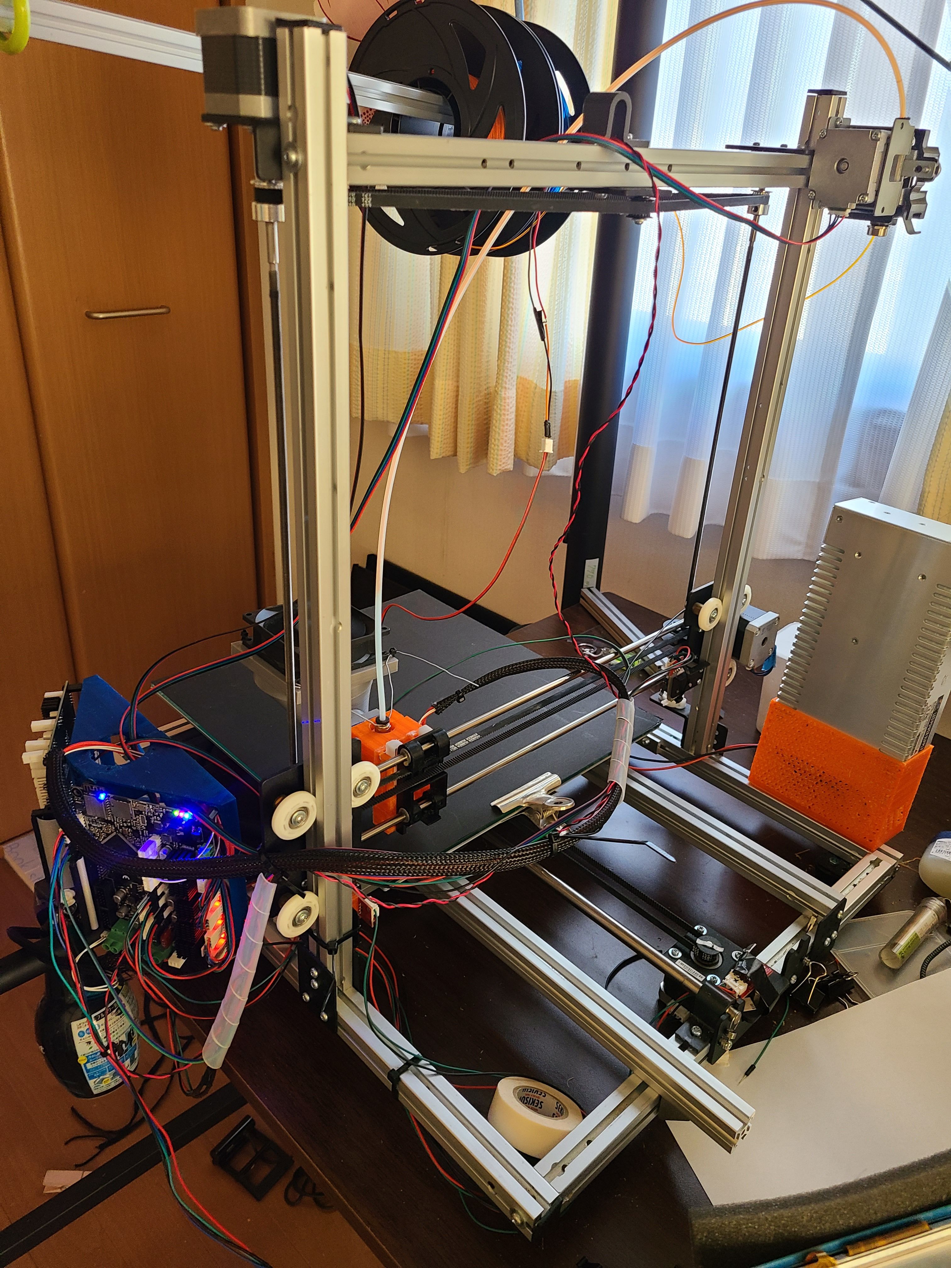
Can you post a photo of the printer?
Can you also share your homing macros and bed.g if you use it? -
@phaedrux Thank you for your reply.
The shape is very similar to my Prusa printer, so it is a Cartesian type.
Photo:
The printer's bed is usually used with a black paper between a glass plate and an aluminium plate.
photo:
The sensor used is an IR probe.
Photo:
Here is the probe I bought
URL:IRSensor
Finally, here is the Bed.g file.; bed.g ; called to perform automatic bed compensation via G32 ; ; generated by RepRapFirmware Configuration Tool v3.3.5 on Sun Nov 14 2021 09:23:54 GMT+0900 (日本標準時) M561 ; clear any existing bed transform M401 ; deploy Z probe if necessary G30 P0 X60 Y30 Z-99999 ; define 4 points in a clockwise direction around the bed, starting near (0,0) G30 P1 X330 Y30 Z-99999 G30 P2 X330 Y290 Z-99999 G30 P3 X60 Y290 Z-99999 G30 P4 X150 Y150 Z-99999 S0 ; finally probe bed centre, and calculate compensation M402 ; retract the Z probe G1 X0 Y0 F5000 ; move the head to the corner (optional) ;M561 ; clear any existing bed transform ;M401 ; deploy Z probe if necessary ;G30 P0 X10 Y10 Z-99999 ; define 4 points in a clockwise direction around the bed, starting near (0,0) ;G30 P1 X10 Y190 Z-99999 ;G30 P2 X190 Y190 Z-99999 ;G30 P3 X190 Y10 Z-99999 ;G30 P4 X100 Y100 Z-99999 S0 ; finally probe bed centre, and calculate compensation ;M402 ; retract the Z probe ;G1 X0 Y0 F5000 ; move the head to the corner (optional) ;M561 ; clear any bed transform ;G29 ; probe the bed and enable compensation -
@kotuo which axis moves the bed, X or Y? It looks like the saddle-shaped bed mesh is in the Y axis, and your probe offset is set in X, but the probe is mounted in front of the nozzle, so it seems the nozzle and carriage are on the Y axis, and the bed moves in X? Normally bed moves in Y, nozzle moves in X.
The Z probe is mounted in front of the hot end. You have a big fan mounted even further out, and long 8mm(?) linear rods. Your bed mesh is saddle shaped (earlier I thought it looked domed, so assumed you had a delta printer), so my guess is that the offset weight of the hot end and fan is causing significant bending of the linear rods, which the offset probe is moving down then back up as it crosses the X axis. The nozzle won’t be moving in Z as much, but will be moving back and forth, as the carriage rotates around the axis, ie printed walls will not be straight.
The best you can do is mount the probe to the side of the X carriage, in line with the nozzle, not in front. Also try to balance out the carriage by putting weight on the back; perhaps move the fan assembly to the back, if possible. It may also be that one, or both, linear rods are not straight. For long axes you really need something that is straight and cannot be bent easily. Linear rod printers don’t scale up well for this reason.
It could also be the weight of the bed causing the bed linear rods to bend, though it looks like that runs on aluminium extrusion.
Ian
Bed-slinger - Mini5+ WiFi/1LC | RRP Fisher v1 - D2 WiFi | Polargraph - D2 WiFi | TronXY X5S - 6HC/Roto | CNC router - 6HC | Tractus3D T1250 - D2 Eth
-
@droftarts Thank you for your reply.
In my printer, the X axis is currently the axis that moves the bed.As @droftarts pointed out, there is a possibility that the large FAN attached to the hot end has a negative effect, so I removed the FAN and measured again.
Here is the resulting image.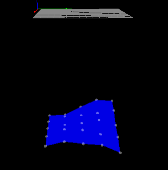
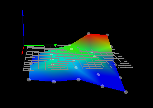
Here are the results after adjusting the height again.
-
Do you actually use bed.g? Or call it with G32 at any point?
Can you post your homeall.g and homez.g files?
When the heightmap has such a large offset it's usually because the mesh has been created without the z axis being homed with the probe first.
Your homing files should home the Z axis with the probe using G30 at the center of the bed to set the Z0 location. Then create a fresh height map.
-
@phaedrux Thank you for your reply.
@phaedrux said in The height map is not created correctly:
Do you actually use bed.g? Or call it with G32 at any point?
I ran G32 and found that P1 and P4 were not probed as the probes were sticking out of the bed.
@phaedrux said in The height map is not created correctly:
homeall.gファイルとhomez.gファイルを投稿できますか?
This is Homeall
; homeall.g
; called to home all axes
;
; generated by RepRapFirmware Configuration Tool v3.3.5 on Sun Nov 14 2021 09:23:55 GMT+0900 (日本標準時)
G91                     ; relative positioning
G1 H2 Z5 F6000          ; lift Z relative to current position
G1 H1 X-305 Y-305 F1800 ; move quickly to X and Y axis endstops and stop there (first pass)
G1 H2 X5 Y5 F6000       ; go back a few mm
G1 H1 X-305 Y-305 F360  ; move slowly to X and Y axis endstops once more (second pass)
G1 H1 Z-305 F360        ; move Z down stopping at the endstop
G90                     ; absolute positioning
G92 Z0                  ; set Z position to axis minimum (you may want to adjust this)

; Uncomment the following lines to lift Z after probing
;G91                    ; relative positioning
;G1 Z5 F100             ; lift Z relative to current position
;G90                    ; absolute positioning
This is Homez
; homez.g
; called to home the Z axis
;
; generated by RepRapFirmware Configuration Tool v3.3.5 on Sun Nov 14 2021 09:23:56 GMT+0900 (日本標準時)
G91 ; relative mode
G1 S2 Z5 F200 ; raise head 4mm to ensure it is above the Z probe trigger height
G90 ; back to absolute mode
G1 X150 Y150 F2000 ; put head over the centre of the bed, or wherever you want to probe
G30 ; lower head, stop when probe triggered and set Z to trigger height

;G91               ; relative positioning
;G1 H2 Z5 F6000    ; lift Z relative to current position
;G1 H1 Z-305 F1800 ; move Z down until the endstop is triggered
;G92 Z0            ; set Z position to axis minimum (you may want to adjust this)

; Uncomment the following lines to lift Z after probing
;G91              ; relative positioning
;G1 Z5 F100       ; lift Z relative to current position
;G90              ; absolute positioning
@phaedrux said in The height map is not created correctly:
When the heightmap has such a large offset it's usually because the mesh has been created without the z axis being homed with the probe first.
Now I understand why the height map was made so low.
@phaedrux said in The height map is not created correctly:
Your homing files should home the Z axis with the probe using G30 at the center of the bed to set the Z0 location. Then create a fresh height map.
Does this mean that I need to do a paper filler test in the centre of the bet and then run 「G92 Z0」 and then 「G29」?
-
@kotuo said in The height map is not created correctly:
Does this mean that I need to do a paper filler test in the centre of the bet and then run 「G92 Z0」 and then 「G29」?
You shouldn't need to set the Z axis 0 manually, as you have a probe to do that, and it looks like when you home Z properly, it works okay. I think the problem is that your homeall.g file is incorrect.
At the moment, your homez.g homes the Z axis in the middle of the bed, with:
G1 X150 Y150 F2000 ; put head over the centre of the bed, or wherever you want to probe
G30 ; lower head, stop when probe triggered and set Z to trigger height
but your homeall.g just sets Z=0 at whatever height the Z is at after homing X and Y:
G92 Z0 ; set Z position to axis minimum (you may want to adjust this)Replace the G92 line in homeall.g with the two lines from homez.g, then a home all should home Z in the middle of the bed. If the nozzle doesn't touch the bed when you move Z to 0, check your probe offset: https://duet3d.dozuki.com/Wiki/Test_and_calibrate_the_Z_probe#Section_Calibrate_the_Z_probe_trigger_height
Your bed mesh looks better, but now shows that the bed is twisted, or that the bed rails are not level (one side rises compared to the other) or that the nozzle carriage twists around the Y axis as it moves from one side to the other (if your bed still moves in X). If your bed has corner adjusters, you can use the manual bed levelling assistant to tell you how far to adjust the bed: https://duet3d.dozuki.com/Wiki/Using_the_manual_bed_levelling_assistant
That should get you closer to a flat bed. It's always best to get the bed as mechanically level as possible, so the bed mesh compensation isn't having to work too hard.
Ian
-
@droftarts Sorry for the delay in replying.
Thank you for your reply.
I have reworked the parts you pointed out.I rewrote homeall.g and it looks like this.
; homeall.g
; called to home all axes
;
; generated by RepRapFirmware Configuration Tool v3.3.5 on Sun Nov 14 2021 09:23:55 GMT+0900 (日本標準時)
G91                     ; relative positioning
G1 H2 Z5 F6000          ; lift Z relative to current position
G1 H1 X-305 Y-305 F1800 ; move quickly to X and Y axis endstops and stop there (first pass)
G1 H2 X5 Y5 F6000       ; go back a few mm
G1 H1 X-305 Y-305 F360  ; move slowly to X and Y axis endstops once more (second pass)
G1 H1 Z-305 F360        ; move Z down stopping at the endstop
G90                     ; absolute positioning
G1 X150 Y150 Z5 F2000 ; put head over the centre of the bed, or wherever you want to probe
G30 ; lower head, stop when probe triggered and set Z to trigger height


;G92 Z0                  ; set Z position to axis minimum (you may want to adjust this)

; Uncomment the following lines to lift Z after probing
;G91                    ; relative positioning
;G1 Z5 F100             ; lift Z relative to current position
;G90                    ; absolute positioning
As a result, when HomeAll is done, after the X and Y axis hit the limit switch, the carriage moves to the centre and is now Z-probed.
The next question is about the probe offset.
This is a CAD simulation of my probe.
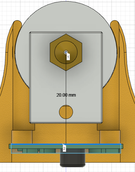
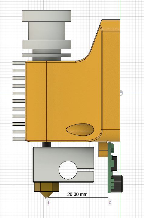
You will probably need to enter X+20 or X-20 as the offset for G31.
I have checked the offset and if I move the probe to where the hot end nozzle is marked, then at +20mm the probe will be in the same position as the nozzle.
I set it to X20 on the G31.
However, I don't think that the Y axis offset is moving from the nozzle to either side. In this case, is it correct to set the Y offset to 0?The next question is about Using the Manual Bed Levelling Assistant.
The prerequisite for Using the Manual Bed Levelling Assistant is
{You need to use the {M671 command to define the X and Y coordinates of the adjusting screw. The M671 command must be specified after the M667 or M669 command in config.g}.
but the adjustment screw on my printer bed is on the inside of the bed.
Is this something I should be concerned about?
Also, there is no M669 in my Config.g. What should I do in this case? -
Is the probe in front or behind the nozzle? To the left or the right?
+X should be to the right, -X to the left, -Y to the front, +Y behind.
@kotuo said in The height map is not created correctly:
but the adjustment screw on my printer bed is on the inside of the bed.
That's fine. Just provide the absolute positions of the screws.
@kotuo said in The height map is not created correctly:
Also, there is no M669 in my Config.g. What should I do in this case?
That's fine. Do nothing.
-
@phaedrux said in The height map is not created correctly:
Is the probe in front or behind the nozzle? To the left or the right?
+X should be to the right, -X to the left, -Y to the front, +Y behind.
Except @kotuo has the bed moving in X, and the extruder carriage moving in Y, so the sensor behind the nozzle is at, I think, X-20 Y0 when the nozzle is at the origin.
@kotuo said in The height map is not created correctly:
Also, there is no M669 in my Config.g. What should I do in this case?
That's fine. Do nothing.
To elaborate on this, M669 sets the printer kinematics. The default is cartesian, which your machine is, so you don’t need M669 explicitly.
Ian
Bed-slinger - Mini5+ WiFi/1LC | RRP Fisher v1 - D2 WiFi | Polargraph - D2 WiFi | TronXY X5S - 6HC/Roto | CNC router - 6HC | Tractus3D T1250 - D2 Eth
-
@kotuo does this picture show the nozzle at X0 Y0?
If the bed is moving in X, and the extruder carriage in Y, this should be the maximum X point, not minimum.Ian
Bed-slinger - Mini5+ WiFi/1LC | RRP Fisher v1 - D2 WiFi | Polargraph - D2 WiFi | TronXY X5S - 6HC/Roto | CNC router - 6HC | Tractus3D T1250 - D2 Eth
-
@droftarts Thank you for your reply.
This picture is taken from the back of the printer.
Y is about -20 places from the maximum
X is about two thirds of the way from the minimum.
In the printer settings, this is the maximum position.
In order to improve the serviceability of the printer, the bed can be moved up to 500mm -
@droftarts Thank you for your reply.
@droftarts said in The height map is not created correctly:
Is the probe in front or behind the nozzle? To the left or the right?
The nozzle is in front of the printer. And the probe is set at 20mm in front from the nozzle.
-
@phaedrux Thank you for your reply.
I now understand the relationship between X and Y. Thank you. -
@droftarts @phaedrux Thank you for your kind remarks to my ignorance.
I finished setting up the M671 today. The result on Bed.g looks like this.
Bed image: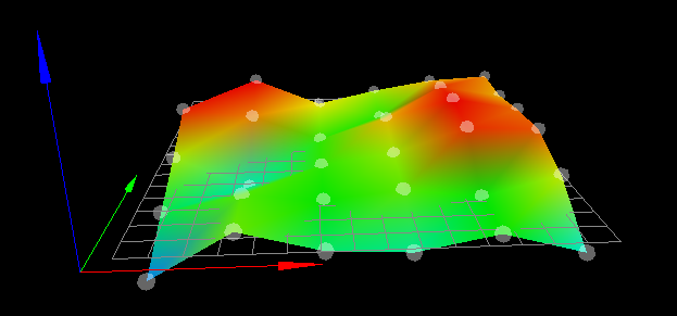
G32Results:G32
Manual corrections required: 0.00 turn up (0.00mm) 0.19 turn down (0.09mm) 0.13 turn down (0.07mm) 0.19 turn down (0.10mm)
Thank you for telling us.
I don't think I could have done so much with my knowledge. -
 undefined kotuo has marked this topic as solved