Mesh Bed Leveling does not work (Core XY with 2 z-axis motors)
-
Hi
I noticed these days, that my new built Core XY printer does not compensate the z-axis error for the first layer (with reprap 3.3). I did a test where I could clearly see that the printer doesn't do anything on the z-axis. I use 2 independent z-axis motors. Not sure if there is a bug in the reprap firmware. On my second printer with 1 z-axis motor I couldn't see any issue here. I also checked if the motors goes to the correct driver.
This is my start code:
M140 S[first_layer_bed_temperature]; set bed temp
M190 S[first_layer_bed_temperature]; wait for bed temp
G32
M104 S[first_layer_temperature]; set extruder temp
G29;
G1 Z30 F5000;
G1 X10 Y0 F30000;
M109 S[first_layer_temperature]; wait for extruder temp
G92 E0 ; reset extrusion distance
G1 Z10 F1000;
G1 X50 Z1 F1000;
G1 X100 Z0.4 F1000 E15;
G1 X200 F1000 E22;
My config file:
; Drives
M569 P0 S0                                             ; physical drive 0 goes forwards
M569 P1 S0                                             ; physical drive 1 goes backwards
M569 P2 S1                                             ; physical drive 2 goes forwards
M569 P3 S1                                             ; physical drive 3 goes backwards
M569 P4 S1                                             ; physical drive 4 goes backwards
M584 X1 Y0 Z2:4 E3                                     ; set drive mapping
M671 X-55:465 Y0:0 S1.5 			       ; leadscrews at left (connected to Z) and right (connected to E1) of X axis
M208 X10:390 Y0:400 				       ; X carriage moves from -5 to 205, Y bed goes from 0 to 200
M350 X16 Y16 Z16 E16:16 I1                             ; configure microstepping with interpolation
M92 X80.00 Y80.00 Z320.00:320.00 E645.00               ; set steps per mm
M566 X600.00 Y600.00 Z200.00:200.00 E300.00            ; set maximum instantaneous speed changes (mm/min)
M203 X30000.00 Y30000.00 Z5000.00:5000.00 E3600.00     ; set maximum speeds (mm/min)
M201 X5000.00 Y5000.00 Z250.00:250.00 E600.00          ; set accelerations (mm/s^2)
M204 P1500 T5000				       ; set printing and travel accelerations
M593 P"daa" F40  				       ; use DAA to cancel ringing at 40.5Hz
M906 X1500 Y1500 Z1200:1200 E700 I30                   ; set motor currents (mA) and motor idle factor in per cent
M84 S30                                                ; Set idle timeout

; Axis Limits
M208 X0 Y0 Z0 S1                                       ; set axis minima
M208 X400 Y400 Z406 S0                                 ; set axis maxima

; Endstops
M574 X1 S1 P"!xstop"                                   ; configure switch-type (e.g. microswitch) endstop for low end on X via pin xstop
M574 Y1 S1 P"!ystop"                                   ; configure switch-type (e.g. microswitch) endstop for low end on Y via pin ystop
M574 Z2 S2                                             ; configure Z-probe endstop for high end on Z

; Z-Probe
M950 S0 C"exp.heater3"                                 ; create servo pin 0 for BLTouch
M558 P9 C"^zprobe.in" H5 F200 T30000                   ; set Z probe type to bltouch and the dive height + speeds
G31 P500 X0 Y35 Z1.85                                  ; set Z probe trigger value, offset and trigger height
M557 X50:350 Y50:350 S50                               ; define mesh grid

; Heaters
M308 S0 P"bedtemp" Y"thermistor" T100000 B3950         ; configure sensor 0 as thermistor on pin bedtemp
M950 H0 C"bedheat" T0                                  ; create bed heater output on bedheat and map it to sensor 0
M307 H0 B0 R0.344 C669.7 D2.52 S1.00 V24.0             ; enable bang-bang mode for the bed heater and set PWM limit
M140 H0                                                ; map heated bed to heater 0
M143 H0 S120                                           ; set temperature limit for heater 0 to 120C
M308 S1 P"e0temp" Y"thermistor" T100000 B4725 C7.06e-8 ; configure sensor 1 as thermistor on pin e0temp
M950 H1 C"e0heat" T1                                   ; create nozzle heater output on e0heat and map it to sensor 1
M307 H1 B0 R2.190 C140.1:137.8 D6.98 S1.00 V24.0       ; disable bang-bang mode for heater  and set PWM limit
M143 H1 S280                                           ; set temperature limit for heater 1 to 280C

; Fans
M950 F0 C"fan0" Q500                                   ; create fan 0 on pin fan0 and set its frequency
M106 P0 S0 I0 H-1                                      ; set fan 0 value. Thermostatic control is turned off
M950 F1 C"fan1"   Q100                                 ; create fan 1 on pin fan1 and set its frequency
M106 P1 S230 H1 T60                                    ; set fan 1 value. Thermostatic control is turned on

; Tools
M563 P0 S"Dragon Hotend" D0 H1 F0                      ; define tool 0
G10 P0 X0 Y0 Z0                                        ; set tool 0 axis offsets
G10 P0 R0 S0                                           ; set initial tool 0 active and standby temperatures to 0C

; Custom settings are not defined
I'm using G32 before G29? To my knowledge this should work.
Many thanks in advance.
Best regards
Michael
-
@buckker said in Mesh Bed Leveling does not work (Core XY with 2 z-axis motors):
Z320.00:320.00
In your config you have multple values for the Z axis. Remove the second values. Only the extruders need independant values.
Can you post your homeall and bed.g?
Do you also have a mesh.g?Can you also send M122 and M98 P"config.g" and post the results?
-
Thanks for your help
I removed the second z value.
Homeall.g
; homeall.g
; called to home all axes
;
; generated by RepRapFirmware Configuration Tool v3.3.5 on Mon Nov 01 2021 20:45:36 GMT+0100 (Mitteleuropäische Normalzeit)
G91                     ; relative positioning
G1 H1 X-405 Y-405 F3000 ; move quickly to X or Y endstop and stop there (first pass)
G1 H1 X-405             ; home X axis
G1 H1 Y-405             ; home Y axis
G1 X5 Y5 F24000         ; go back a few mm
G1 H1 X-405 F360        ; move slowly to X axis endstop once more (second pass)
G1 H1 Y-405             ; then move slowly to Y axis endstop
G90                     ; absolute positioning
G1 X200 Y165 F24000     ; go to first bed probe point and home Z
G30                     ; home Z by probing the bed

; Uncomment the following lines to lift Z after probing
;G91                    ; relative positioning
;G1 Z5 F400             ; lift Z relative to current position
;G90                    ; absolute positioning
bed.g
G28 ; home
M401 ; deploy Z probe (omit if using bltouch)
G30 P0 X10 Y200 Z-99999 ; probe near a leadscrew, half way along Y axis
G30 P1 X390 Y200 Z-99999 S2 ; probe near a leadscrew and calibrate 2 motors
M402 ; retract probe (omit if using bltouch)


; bed.g
; called to perform automatic bed compensation via G32
;
; generated by RepRapFirmware Configuration Tool v3.3.5 on Mon Nov 01 2021 20:45:36 GMT+0100 (Mitteleuropäische Normalzeit)
;M561 ; clear any bed transform
;G29  ; probe the bed and enable compensation
M122:
M122
=== Diagnostics ===
RepRapFirmware for Duet 2 WiFi/Ethernet version 3.3 (2021-06-15 21:44:54) running on Duet WiFi 1.02 or later
Board ID: 08DLM-996RU-N85S4-7JKDL-3S06S-18BMN
Used output buffers: 3 of 24 (16 max)
=== RTOS ===
Static ram: 23876
Dynamic ram: 75052 of which 0 recycled
Never used RAM 15488, free system stack 180 words
Tasks: NETWORK(ready,13.6%,247) HEAT(delaying,0.0%,314) Move(notifyWait,0.1%,364) MAIN(running,85.5%,445) IDLE(ready,0.8%,29), total 100.0%
Owned mutexes:
=== Platform ===
Last reset 00:02:02 ago, cause: software
Last software reset at 2021-12-23 07:58, reason: User, GCodes spinning, available RAM 15488, slot 2
Software reset code 0x0003 HFSR 0x00000000 CFSR 0x00000000 ICSR 0x0041f000 BFAR 0xe000ed38 SP 0x00000000 Task MAIN Freestk 0 n/a
Error status: 0x00
Aux0 errors 0,0,0
Step timer max interval 0
MCU temperature: min 16.2, current 18.6, max 18.8
Supply voltage: min 23.9, current 24.1, max 24.3, under voltage events: 0, over voltage events: 0, power good: yes
Heap OK, handles allocated/used 0/0, heap memory allocated/used/recyclable 0/0/0, gc cycles 0
Driver 0: position 0, standstill, SG min/max not available
Driver 1: position 0, standstill, SG min/max not available
Driver 2: position 0, standstill, SG min/max not available
Driver 3: position 0, standstill, SG min/max not available
Driver 4: position 0, standstill, SG min/max not available
Driver 5: position 0
Driver 6: position 0
Driver 7: position 0
Driver 8: position 0
Driver 9: position 0
Driver 10: position 0
Driver 11: position 0
Date/time: 2021-12-23 08:00:34
Cache data hit count 4294967295
Slowest loop: 8.59ms; fastest: 0.17ms
I2C nak errors 0, send timeouts 0, receive timeouts 0, finishTimeouts 0, resets 0
=== Storage ===
Free file entries: 10
SD card 0 detected, interface speed: 20.0MBytes/sec
SD card longest read time 3.3ms, write time 2.1ms, max retries 0
=== Move ===
DMs created 83, maxWait 0ms, bed compensation in use: none, comp offset 0.000
=== MainDDARing ===
Scheduled moves 0, completed moves 0, hiccups 0, stepErrors 0, LaErrors 0, Underruns [0, 0, 0], CDDA state -1
=== AuxDDARing ===
Scheduled moves 0, completed moves 0, hiccups 0, stepErrors 0, LaErrors 0, Underruns [0, 0, 0], CDDA state -1
=== Heat ===
Bed heaters = 0 -1 -1 -1, chamberHeaters = -1 -1 -1 -1
=== GCodes ===
Segments left: 0
Movement lock held by null
HTTP is idle in state(s) 0
Telnet is idle in state(s) 0
File is idle in state(s) 0
USB is idle in state(s) 0
Aux is idle in state(s) 0
Trigger is idle in state(s) 0
Queue is idle in state(s) 0
LCD is idle in state(s) 0
Daemon is idle in state(s) 0
Autopause is idle in state(s) 0
Code queue is empty.
=== Network ===
Slowest loop: 21.19ms; fastest: 0.00ms
Responder states: HTTP(2) HTTP(0) HTTP(0) HTTP(0) FTP(0) Telnet(0), 0 sessions
HTTP sessions: 1 of 8
- WiFi -
Network state is active
WiFi module is connected to access point
Failed messages: pending 0, notready 0, noresp 0
WiFi firmware version 1.23
WiFi MAC address 50:02:91:de:7c:41
WiFi Vcc 3.43, reset reason Turned on by main processor
WiFi flash size 4194304, free heap 24200
WiFi IP address 192.168.0.29
WiFi signal strength -74dBm, mode none, reconnections 0, sleep mode modem
Clock register ffffffff
Socket states: 0 0 0 0 0 0 0 0
M98:
M98 P"config.g"
HTTP is enabled on port 80
FTP is disabled
TELNET is disabled
Error: in file macro line 29 column 22: M350: array too long, max length = 1
I find the error in the config.g : M350 X16 Y16 Z16 E16:16 I1 I corrected it to M350 X16 Y16 Z16 E16 I1
-
You have the leadscrew positions defined at Y0 in config, but you probe at Y200 in bed.g
Something is wrong between those two - the Y coordinates should match?
I think the probe points should be dead in line with the leadscrews and as close as possible to them, for best levelling accuracy.
-
Yes, you're right. of course the values should match. I changed it to Y200 in the config.g. Thanks!
-
@buckker said in Mesh Bed Leveling does not work (Core XY with 2 z-axis motors):
G28 ; home M401 ; deploy Z probe (omit if using bltouch) G30 P0 X10 Y200 Z-99999 ; probe near a leadscrew, half way along Y axis G30 P1 X390 Y200 Z-99999 S2 ; probe near a leadscrew and calibrate 2 motors M402 ; retract probe (omit if using bltouch)
there is a comment in bed.g to remove M401 and M402 lines if you use the BLTouch and according to config.g you're using BLTouch, so I would remove the lines. BLTouch deploys and retracts himself by running deployprobe.g and retractprobe.g (please check them).
If you don't have retractprobe.g and deployprobe.g, the content is described in https://duet3d.dozuki.com/Wiki/Connecting_a_Z_probe#Section_BLTouch (one M280 line each).
-
I removed the unnecessary commands. But it don't make any difference.
The probing works normal. I can also see the height map. But the printer does not use the height map during the print...
-
@buckker said in Mesh Bed Leveling does not work (Core XY with 2 z-axis motors):
I removed the unnecessary commands. But it don't make any difference.
The probing works normal. I can also see the height map. But the printer does not use the height map during the print...
while
probing/mesh compensationprinting after probing, and you make M122, it is reported whether mesh compensation is active:=== Move ===
DMs created 83, maxWait 0ms, bed compensation in use: none, comp offset 0.000Did you make your M122 while you probed and if not, can you please check it?I would call a T0 to select the tool, then G29. => you're right @rjenkinsgb G29 S0 (although G29 withoug mesh.g runs G29 S0 automatically)
-
Try changing G29 in your start code to either G29 S0 (create new heightmap) or G29 S2 (load existing heightmap)
I must admit, the mesh levelling is the one problem I'm still trying to work through in my dual Z drive CoreXY toolchanging machine - though that's a probe problem to do with creating it accurately rather than it working or not.
-
I tried this several minutes ago, but It doesn't help:
; generated by PrusaSlicer 2.4.0-beta1+win64 on 2021-12-22 at 12:54:39 UTC

;

; external perimeters extrusion width = 0.45mm
; perimeters extrusion width = 0.45mm
; infill extrusion width = 0.45mm
; solid infill extrusion width = 0.45mm
; top infill extrusion width = 0.40mm
; first layer extrusion width = 0.45mm

M107
;TYPE:Custom
G29 S2;
M140 S55; set bed temp
M190 S55; wait for bed temp
G32
M104 S220; set extruder temp
G29 S0;
G1 Z30 F5000;
G1 X10 Y0 F30000;
M109 S220; wait for extruder temp
G29 S1;
G92 E0 ; reset extrusion distance
G1 Z10 F1000;
G1 X50 Z1 F1000;
G1 X100 Z0.4 F1000 E15;
G1 X200 F1000 E22;


G21 ; set units to millimeters
G90 ; use absolute coordinates
M82 ; use absolute distances for extrusion
G92 E0
M572 D0 S0.05;
M107
;LAYER_CHANGE
;Z:0.2
;HEIGHT:0.2
G1 E-1.2 F3600
G92 E0
G1 Z.2 F30000
G1 Z.4
G1 X10.225 Y10.225
G1 Z.2
G1 E1.2 F3600
;TYPE:External perimeter
;WIDTH:0.45
G1 F2100
G1 X389.775 Y10.225 E13.53342
G1 X389.775 Y389.775 E25.86685
G1 X10.225 Y389.775 E38.20027
G1 X10.225 Y10.285 E50.53174
G1 X10.975 Y10.975 F30000
G1 F2100
G1 X389.025 Y10.975 E62.81642
Clear height map a the begin, probing and at the loading it..
-
@buckker you have nowhere selected the tool and the slicer doesn't select it too, I would add T0 to the end of config.g
I would then try a simple G29 S0 after rebooting and homing, then checking mesh probing status by making M122 while probing.
-
I checked the following things:
M122 during probing:
DMs created 83, maxWait 9ms, bed compensation in use: none, comp offset 0.000M122 during printing:
DMs created 83, maxWait 18ms, bed compensation in use: mesh, comp offset 0.000this is the tool section from the config..g:
; Tools
M563 P0 S"Dragon Hotend" D0 H1 F0                      ; define tool 0
G10 P0 X0 Y0 Z0                                        ; set tool 0 axis offsets
G10 P0 R0 S0                                           ; set initial tool 0 active and standby temperatures to 0C
I add a T0 to my g-code file:
; generated by PrusaSlicer 2.4.0-beta1+win64 on 2021-12-22 at 12:54:39 UTC

;

; external perimeters extrusion width = 0.45mm
; perimeters extrusion width = 0.45mm
; infill extrusion width = 0.45mm
; solid infill extrusion width = 0.45mm
; top infill extrusion width = 0.40mm
; first layer extrusion width = 0.45mm

M107
;TYPE:Custom
T0;
M140 S55; set bed temp
M190 S55; wait for bed temp
G32
M104 S220; set extruder temp
G29 S0;
G1 Z30 F5000;
G1 X10 Y0 F30000;
M109 S220; wait for extruder temp
G92 E0 ; reset extrusion distance
G1 Z10 F1000;
G1 X50 Z1 F1000;
G1 X100 Z0.4 F1000 E15;
G1 X200 F1000 E22;


G21 ; set units to millimeters
G90 ; use absolute coordinates
M82 ; use absolute distances for extrusion
G92 E0
M572 D0 S0.05;
I will modify the gcode to your ideas.
Actually I can't see any z-axis compensating during the print....
-
@buckker so M122 says that mesh compensation is active.
I can think of the following possibilites
- the bed is plain enough so you don't see compensation
- the probe-nozzle offset is wrong, so the compensation is at the wrong place
- printing outside mesh probing M557 X50:350 Y50:350 S50
The offset is set at G31 X, Y, Z values. Your values are X0 Y35 Z1.85, which means the BLTouch should be at the same X position and 35 mm behind the nozzle, when you look at the printer and X plus is to the right and Y plus is to the back.
For the plain bed, please check the heightmap.csv, it is viewable in the DWC (Duet web control browser application).
The mesh was measured starting at (50,50), you may look at the wrong points,
-
My conclusion after a few tests....:
- the printer compensates now some z-axis deviation. I put a dial gauge on the heat bed. I could see, that the z-axis moves during the printing. But the nozzle touches the bed at one corner. At the other corner the first layer is somewhere in the air... It seems that It compensates in the wrong direction... How is this possible? G32 works fine, it compensates in the correct direction.
The BL Touch is placed behind the nozzle, only y-axis offset:

some other pictures:


Heightmap:

@joergs5 said in Mesh Bed Leveling does not work (Core XY with 2 z-axis motors):
printing outside mesh probing M557 X50:350 Y50:350 S50
Whats actually happens if I print outside the probing area?
-
@buckker plaese see my last comment from previous post, I added the possibility that the mesh measurement starts at 50,50, so you may have not measured the whole area. Please try to measure the whole M208 area (please be careful, the BLTouch/extruder needs some room...).
I cannot remember, whether M557 coordinates refer to the M208 or to the BLTouch positions.
-
@buckker BTW congratulations using good measurement equipment!
-
@buckker said in Mesh Bed Leveling does not work (Core XY with 2 z-axis motors):
Whats actually happens if I print outside the probing area?
I looked into the source Grid.cpp function GetInterpolatedHeightError(): my understanding is, the last mesh point in this direction is used as reference height. E.g. if (50,50) to (350,350) have mesh points, than for (0,200) the point (50,200) is taken as height.
-
@buckker one more aspect I can think of is if your Z axis is driven by something like a worm drive, that direction changes have some play (backlash). This would cause unexpected movements.
You can check whether there is compensation directly by checking the Z motor position: M114 has a Count value, the third one is the motor position of Z. The counter is set at homing and depends on motor position and M92 value. So you know the firmware's value and not depend on the reality Z position.
-
Yes, Tesa really produces very high quality measurement equipment
")
I modified the probing area with more points. But it also doesn't help. I also print some smaller test parts (cubic with 280mm x 280mm). With this dimensions the part is 100% in the probed area. Same result...
I also checked with the dial gauge the travel of the z-axis. Both motors compensate some deviation. The direction should be also fine. But it was not able to compare the z-axis absolute travel measured by the dial gauge with the height map. It seems that the printer compensate some deviation, but no enough..
I use a belt driven gearbox for the z-axis (4:1). I will check the backlash of the axis.
actual printing result:

height map for this part:
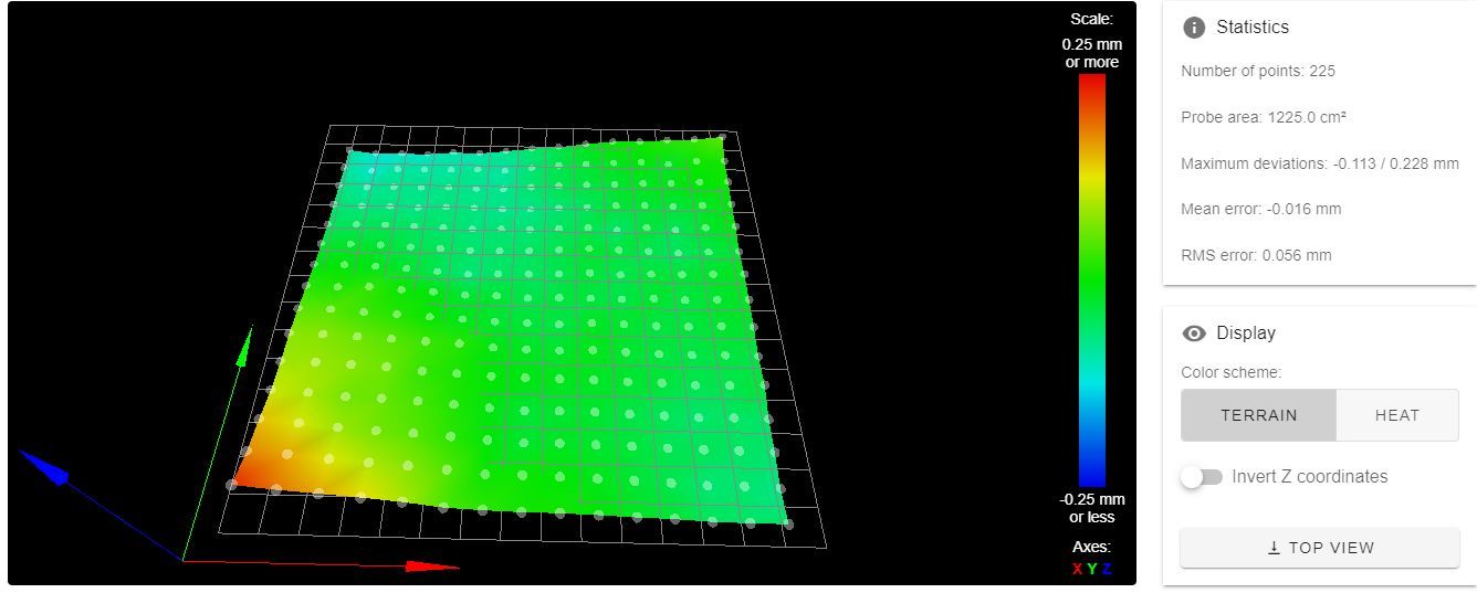
One thing confused me: at the left front corner, the layer should stick very good (+0.2mm offset), the nozzle should have nearly zero gap without mesh bed compensating (if I print at 0.2mm layer height). But actually the layer is too far away from the build plate... I don't understand this...
I will run a print with disabling mesh bed compensation
-
@buckker said in Mesh Bed Leveling does not work (Core XY with 2 z-axis motors):
confused me: at the left front corner, the layer should stick very good (+0.2mm offset),
is this the reality (bed uneven) or is it a measurement error? A good lineal, best would be a hair lineal, could give you the answer. Or a measuring plate together with your gauge. Or maybe you have an additional linear guide, mounting the gauge, parallel to the bed, allows measuring the bed.
I suspect the two linear guides of Y are not in one plane, too. (left is higher in front, right one is higher in the back). I use feeler gauge for fine tuning. You don't have a reference, however. I would try between 0.1 and 0.2 mm and then decide by bed measuring (mesh probing or gauge).
An additonal topic you can check is whether the bed is sliding smooth enough. I. e. the distance of the two opposite linear guides need to have a little play. Otherwise a direction change of Z stepper will produce a little gap, depending how high the belt tension is. The bed should not be fixed with screws, because bed expansion by temperature will change the distance between the linear guides.