Closed Loop Motors SYNC problems
-
Hello all,
We have built a giant size Delta 3D printer finally finished.I have a problem that I could not figure out. It does print straight wall vertical objects perfectly. however, it starts messing up like layer shifting. But I use closed-loop servo-stepper motors. It is almost impossible to shift, otherwise, it will fall in error. As you have seen in the photos, there or no mechanical issue I assume. Because it does print vertical walls precisely. However, when complicated parts with infill, it messes like there are mechanical losses. As I checked many times. There are no mechanical issues too.
Finally, I conclude the closed-loop motors acceleration causing the sync problem then, delays and these unpleasant details occurrence. The longer drive axis delays due to the acceleration and other axes cannot meet on the desired position
Is there any other possibility you may come up with? otherwise, what could it be? if motors sync problems, how can I sync them ?
As seen examples below. vertical walls print perfectly on-shell printing only. Then why could be the reason bad results on others?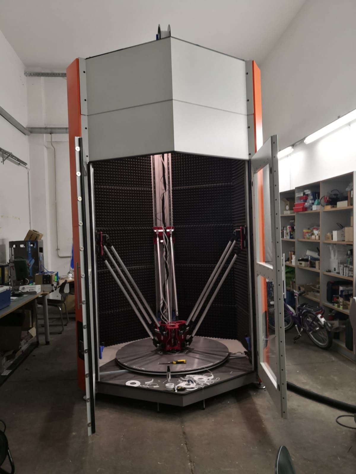
Perfect test printed
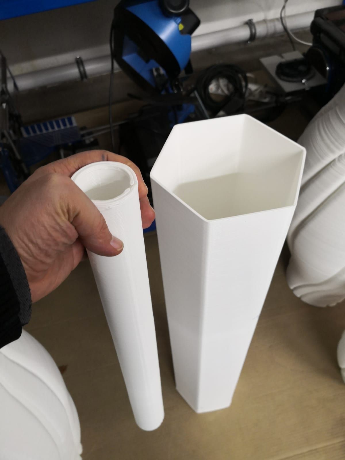
failed prints with infill. as seen even the cylindrical wall defected.
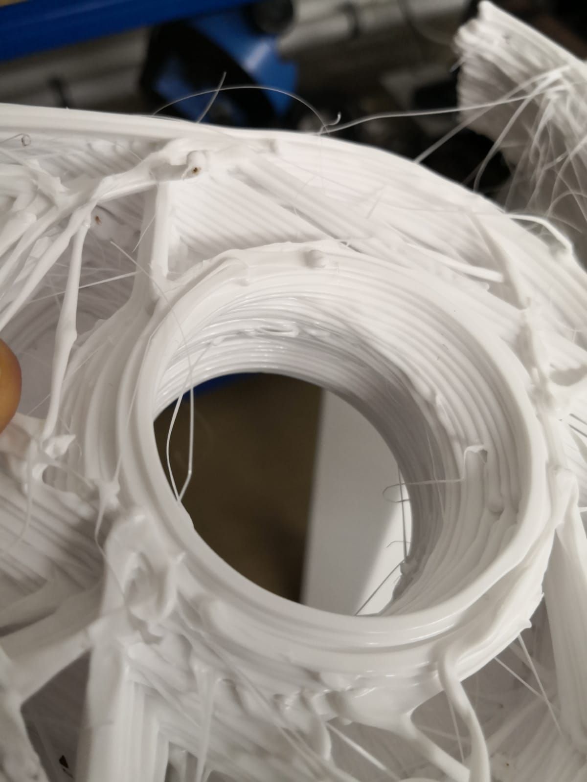
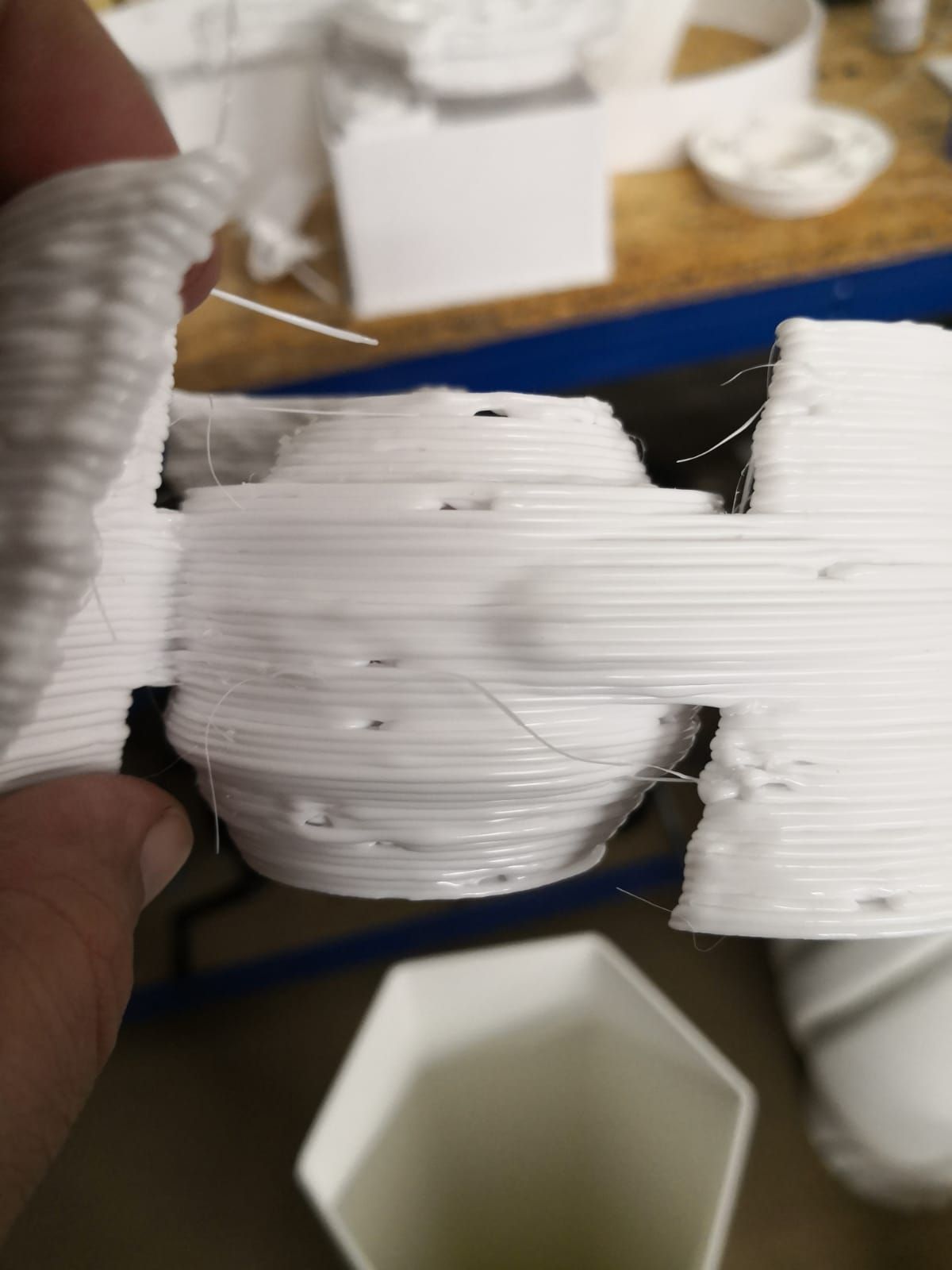
Asymetry is very much visible. however the verticals prints perfectly.

layer shift of the asymetry also visible here.
Kind Regards -
@sozkan can you post your config and the part number of the drivers you are using?
Owns various duet boards and is the main wiki maintainer for the Teamgloomy LPC/STM32 port of RRF. Assume I'm running whatever the latest beta/stable build is
-
@sozkan Also, what Duet boards and what motors, power supply voltage etc?
-
@jay_s_uk said in Closed Loop Motors SYNC problems:
@sozkan can you post your config and the part number of the drivers you are using?
This is the firmware I am using. I am thinking to decrease acceleration for the trial. However I am not sure about it.
Drivers ACT-Motor HBS86H motors NEMA34-Step-34SSM5460-EC1000-Closed-HBS86H-Stepper
more details:
https://www.amazon.de/-/en/NEMA34-Step-34SSM5460-EC1000-Closed-HBS86H-Stepper/dp/B07G9FZZJD/ref=sr_1_1?crid=QDZPWX8SBGWU&keywords=act+motor+hybrid&qid=1641911322&sprefix=act+motor+hybrid%2Caps%2C56&sr=8-1the controller is Duet 2 wifi with external breakoutbard for drivers.
; Configuration file for Duet WiFi (firmware version 3) ; executed by the firmware on start-up ; ; generated by RepRapFirmware Configuration Tool v3.1.4 on Sun Sep 27 2020 20:52:39 GMT+0200 (Central European Summer Time) ; General preferences G90 ; send absolute coordinates... M83 ; ...but relative extruder moves M550 P"Giant3D" ; set printer name M665 L1200.000:1200.000:1200.000 R603.000 H1298.70 B500.0 X0.000 Y0.000 Z0.000 ; Set delta radius, diagonal rod length, printable radius and homed height H1298.25 mm thermal expension. M666 X0.000 Y0.000 Z0.000 A0.00 B0.00 ; put your endstop adjustments here, or let auto calibration find them ; Network ;M551 P"" ; set password ;M552 P0.0.0.0 S1 ; enable network, use DHCP M552 S1 ; enable network M586 P0 S1 ; enable HTTP M586 P1 S0 ; disable FTP M586 P2 S0 ; disable Telnet ; Drives M569 P1 S1 R1 T3:3:5:0 ; Extruder drive 0 goes Forward M569 P2 S1 R0 T2.5:2.5:6:6 ; X:A drive 1 goes Forward M569 P3 S1 R0 T2.5:2.5:6:6 ; Y:B drive 2 goes Forward M569 P4 S1 R0 T2.5:2.5:6:6 ; Z:C physical drive 3 goes Forward M584 X6 Y7 Z8 E5 ; set drive mapping M350 X1 Y1 Z1 E1 I1 ; configure microstepping without interpolation M92 X228.5714 Y228.5714 Z228.5714 E304.44 ; set steps per mm (3200/140) * 10 = 228.5714 ; 3200 step per rev ; 140 mm one rev pulley ;1:10 ratio gearbox M566 X1000.00 Y1000.00 Z1000.00 E1000.00 ; set maximum instantaneous speed changes (mm/min) M203 X2500.00 Y2500.00 Z2500.00 E2500.00 ; set maximum speeds (mm/min) M201 X400.00 Y400.00 Z400.00 E1000.00 ; set accelerations (mm/s^2) M906 X800 Y800 Z800 E800 I30 ; set motor currents (mA) and motor idle factor in per cent M84 S30 ; Set idle timeout ; Axis Limits M208 Z0 S1 ; set minimum Z ; Endstops M574 X2 S1 P"xstop" ; configure active-high endstop for high end on X via pin xstop M574 Y2 S1 P"ystop" ; configure active-high endstop for high end on Y via pin ystop M574 Z2 S1 P"zstop" ; configure active-high endstop for high end on Z via pin zstop ; Z-Probe M558 P8 C"!zprobe.in" H50 F220 T1000 ; set Z probe type to unmodulated and the dive height + speeds ;M558 H30 ;*** Remove this line after delta calibration has been done and new delta parameters have been saved G31 P500 X42.43 Y-42.43 Z1.71 ; Circular 60 mm radious, 42.43 mm set Z probe trigger value, offset and trigger height M557 R450 S200 ; define mesh grid ; Bed Heater M308 S0 P"bedtemp" Y"thermistor" T100000 B3950 ; configure sensor 0 as thermistor on pin bedtemp M950 H0 C"bedheat" T0 ; create bed heater output on bedheat and map it to sensor 0 ;M307 H0 B1 S1 ; enable bang-bang mode for the bed heater and set PWM limit M307 H0 A233.3 C508.3 D160 S1.00 V24.3 B1 M140 H0 ; map heated bed to heater 0 M143 H0 S100 ; set temperature limit for heater 0 to 120C ; HotEnd M308 S1 P"spi.cs1" Y"rtd-max31865" ; configure sensor 1 as PT100 on pin e0temp M308 S2 P"spi.cs2" Y"rtd-max31865" ; configure sensor 2 as PT100 on pin e1temp M950 H1 C"e0heat" T1 ; create nozzle heater output on e0heat and map it to sensor 1 M950 H2 C"e1heat" T2 ; create nozzle heater output on e1heat and map it to sensor 2 ;M307 H1 B0 S0.50 ; disable bang-bang mode for heater and set PWM limit ;M307 H2 B0 S0.50 ; disable bang-bang mode for heater and set PWM limit ;M307 H1 A1137.2 C141.7 D8.4 S1.00 V24.3 B0 M307 H1 A550 C180 D2.0 S0.35 V24.3 B0 M307 H2 A550 C239 D2.7 S0.5 V24.3 B0 ;M301 H1 P5 I0.5 D1 ; Set PID values ;M301 H2 P5 I0.5 D1 ; Set PID values M143 H1 S480 ;Set temperature max temp: M143 H2 S480 ;Set temperature max temp: ; Fans M950 F0 C"fan0" Q500 ; create fan 0 on pin fan0 and set its frequency M106 P0 S1 H2:1 T45 ; set fan 0 value. Thermostatic control is turned on M570 S240 ; wait 120 seconds for it to get close to the set temperature. If it takes longer than this, raise a heater fault. ;M570 H1 P4 T15 ; Tools M563 P0 D0 H1:2 F0 S"Typhoon" ; define tool 0 G10 P0 X0 Y0 Z0 ; set tool 0 axis offsets G10 P0 R0 S0 ; set initial tool 0 active and standby temperatures to 0C ; Custom settings are not defined ; Miscellaneous M575 P1 S1 B57600 ; enable support for PanelDue ;M500 ; Save the parameters to non-volatile memory M501 ; load saved parameters from non-volatile memory M911 S10 R11 P"M913 X0 Y0 G91 M83 G1 Z3 E-5 F1000" ; set voltage thresholds and actions to run on power loss T0 ; select first tool ; Bunun maksadi sadece enable konumuna ulasmasi icin motorlari uyandirmak. ;G91 ; relative positioning ;G1 H2 X-0.1 Y-0.1 Z-0.1 F1000 ; go down a few mm -
@jay_s_uk Power for each driver separately 60V recommended by the motor manufacturer. For the duet, the board is 24V.
-
@sozkan you're setting the pulse width for the external drivers on drives 1, 2, 3 and 4 but then you're using drives 5, 6, 7 and 8
You therefore need to adjust your M569's to use P5, P6, P7 and P8 -
@jay_s_uk said in Closed Loop Motors SYNC problems:
5, P6, P7 and P8
However, you have suggested me at the beginning also. I did this again but it seems, the motors not functioning correct. I send a command to run 100 mm now it is going 90.
Motors generate horrible noise and it is not going the distance it should.By accidentally I realized this "P1, P2, P3, P4" is an unknown reason working correctly, motor smooth moves and correct in dimensions. It seems kind of a bug in that board that I am using I believe.
-
@sozkan except its not working correctly as you are losing steps
-
@jay_s_uk said in Closed Loop Motors SYNC problems:
@sozkan except its not working correctly as you are losing steps
Yes, the settings you recommended are generating noisy step signals on the board. Seems steps were messed on the board before the driver. Hower the present settings I set and worked surprisingly with smooth and precise with vertical wall shell spiral printings except for the problematic results on the solid or far detailed printings.
I think it should not lose a step on the driver. Because these motors are designed to work failsafe. Because it has an encoder and incases of step loose or overdrive, closed-loop system alarm, and stops already.
I am thinking to upgrade the new version duet board if I have to.
-
@sozkan but if the pulse width etc are wrong then the driver wont step as desired and you'll get the outcome you're getting.
I suggest you revisit the correct settingsOwns various duet boards and is the main wiki maintainer for the Teamgloomy LPC/STM32 port of RRF. Assume I'm running whatever the latest beta/stable build is
-
It's a little difficult to check without a data sheet for the motor driver you are using, but I'll try to explain.
The signals from the DUet to the motor driver have to be the right length or the motor driver will not recognize that the Duet is asking it to take a step.
Imagine that the motor driver needed a STEP signal to be one-second long to know it needs to take a step. (I know that's a long time, but it's just for imagination.)
If you send a STEP signal that is only one-half-second long, the motor driver will not know it needs to take a step, and your part will be printed incorrectly even though your motor driver is closed-loop and cannot miss a step.
So, you need to get the "Taa:bb:cc:dd" timing parameters correct in the M569 command.
Do you have a data sheet for the motor driver that shows the timing values?
-
@sozkan I think @jay_s_uk is saying that you had two errors:
1 - you were setting step pulses for the wrong drivers. So you were running on the RRF default ones which just about worked at low speeds, but the step timing etc is not suitable for fast infil sections etc.
2 - the step timings you are now setting are not correct for your motors so its missing even more steps.It doesn't matter how perfect your closed loop control is, if the drivers can't interpret the step pulses coming from the Duet, it will not keep up and so will move fewer steps (or maybe even in the wrong direction)
-
@jay_s_uk said in Closed Loop Motors SYNC problems:
@sozkan but if the pulse width etc are wrong then the driver wont step as desired and you'll get the outcome you're getting.
I suggest you revisit the correct settingsI know it should be one correct setting. However, even the correct settings as suggested already seem not working at this setup. I had no remedy other than to return to the present worked settings. If it was pulse width incompatibility, it should not be worked on both already.
-
@sozkan i am sorry but I can't help you any further then.
hopefully someone else can...Owns various duet boards and is the main wiki maintainer for the Teamgloomy LPC/STM32 port of RRF. Assume I'm running whatever the latest beta/stable build is
-
I found a data sheet with the timing values on Page #12.
It says 2.5:2.5:6:6 should work, but let's try slower than that so that if your drive current through the motor controller's internal LED is a bit low it will still work.
- Can you tell us how you have the Duet wired to the Motor controller please?
Try this and see if it helps:
; Drives

M569 P5 S1 R1 T10:10:10:10  ; Extruder drive 0 goes Forward
M569 P6 S1 R0 T10:10:10:10  ; X:A drive 1 goes Forward
M569 P7 S1 R0 T10:10:10:10  ; Y:B drive 2 goes Forward
M569 P8 S1 R0 T10:10:10:10  ; Z:C physical drive 3 goes Forward
Make some slow moves and see if the motors sound good and move the correct distance.
Then try some faster moves. At some speed, things will start to fail and we can help adjust to get better numbers.
You need to get slow moves sounding nice and moving the correct distance first.
SeemeCNC Rostock Max V3 converted to V3.2 with a Duet2 Ethernet Firmware 3.2 and SE300
-
@jay_s_uk said in Closed Loop Motors SYNC problems:
@sozkan i am sorry but I can't help you any further then.
hopefully someone else can...Thank you very much for your effort and kind suggestion, I really appreciate it.
I will first try with different acceleration. I also find on some other sources, they called ghosting. Delays due to individual acceleration may cause deflection. You know as delta, some of the axes have to run very fast even for a few millimeters compared to another axis to catch coordinates. So I try to decrease acceleration to see the difference. I will get a newer version Duet board and check with suggested settings aswell.
-
@sozkan if you want to use the duet 3 boards you'll also need 1XD external boards as theres no way to connect external drivers to them
I would also suggest that that would make no difference to your current issueOwns various duet boards and is the main wiki maintainer for the Teamgloomy LPC/STM32 port of RRF. Assume I'm running whatever the latest beta/stable build is
-
@alankilian said in Closed Loop Motors SYNC problems:
I found a data sheet with the timing values on Page #12.
It says 2.5:2.5:6:6 should work, but let's try slower than that so that if your drive current through the motor controller's internal LED is a bit low it will still work.
- Can you tell us how you have the Duet wired to the Motor controller please?
Try this and see if it helps:
; Drives

M569 P5 S1 R1 T10:10:10:10  ; Extruder drive 0 goes Forward
M569 P6 S1 R0 T10:10:10:10  ; X:A drive 1 goes Forward
M569 P7 S1 R0 T10:10:10:10  ; Y:B drive 2 goes Forward
M569 P8 S1 R0 T10:10:10:10  ; Z:C physical drive 3 goes Forward
Make some slow moves and see if the motors sound good and move the correct distance.
Then try some faster moves. At some speed, things will start to fail and we can help adjust to get better numbers.
You need to get slow moves sounding nice and moving the correct distance first.
I will try the T values for sure.
I set the connection based on the suggestion here in this thread: https://forum.duet3d.com/topic/18918/giant-delta-printer-slow-homing-issue/37
However, it is difficult to give a picture of the present stage due to the enclosure.
-
@alankilian said in Closed Loop Motors SYNC problems:
I found a data sheet with the timing values on Page #12.
It says 2.5:2.5:6:6 should work, but let's try slower than that so that if your drive current through the motor controller's internal LED is a bit low it will still work.
- Can you tell us how you have the Duet wired to the Motor controller please?
Try this and see if it helps:
; Drives

M569 P5 S1 R1 T10:10:10:10  ; Extruder drive 0 goes Forward
M569 P6 S1 R0 T10:10:10:10  ; X:A drive 1 goes Forward
M569 P7 S1 R0 T10:10:10:10  ; Y:B drive 2 goes Forward
M569 P8 S1 R0 T10:10:10:10  ; Z:C physical drive 3 goes Forward
Make some slow moves and see if the motors sound good and move the correct distance.
Then try some faster moves. At some speed, things will start to fail and we can help adjust to get better numbers.
You need to get slow moves sounding nice and moving the correct distance first.
I really appreciate your help. Motor Sounds even better and smooth stronger also precise on moves. Now I am testing the printing results. Let see how it works. I can later share the video.
All my best to all of you. I could not achieve this without your help.
The only problem is the extruder drive which is provided by the dyze design a simple stepper motor. It seems not moving.
-
@sozkan By the way I have reduced the acceleration value from 1000 to 250. It was before the Pulse width changes. It seems was also helped to correct moves. But I am not very sure.