Servo Configuration Check
-
Please try M950 S1 C"!duex.pwm2" but without the !
And you're for sure using the pwm2 header?
Photo of your wiring?
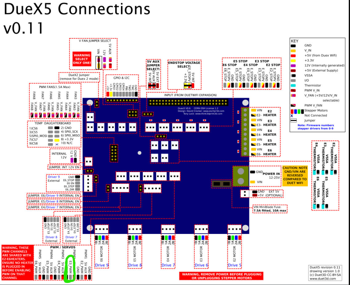
https://docs.duet3d.com/duet_boards/duet_2_expansion/duex_wiring_v0.11_d1.0.png
-
Do you have the ground of the 5 Volt output connected to the ground on the Duet?
If it's isolated then you would need the grounds tied together.
(somewhat unlikely, but who knows)SeemeCNC Rostock Max V3 converted to V3.2 with a Duet2 Ethernet Firmware 3.2 and SE300
-
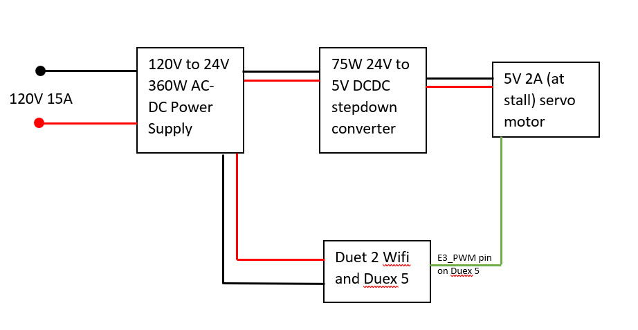
@phaedrux Tried without the ! and here is my wiring diagram and circled the pin on the duex to be safe. Still no dice.
-
@alankilian just posted my abridged wiring diagram above. I don't think that's isolated, but maybe?
-
@jrcl said in Servo Configuration Check:
@alankilian just posted my abridged wiring diagram above. I don't think that's isolated, but maybe?
Do you perhaps have an oscilloscope you could check the PWM signal with? It may not be meeting the requirements for your servo.
Frederick
-
@fcwilt I don't unfortunately. I'm no electrical engineer, but could I use some sort of amplification module on the signal? Not sure if PWM signals work like that/or can be amplified like that.
-
@jrcl said in Servo Configuration Check:
@fcwilt I don't unfortunately. I'm no electrical engineer, but could I use some sort of amplification module on the signal? Not sure if PWM signals work like that/or can be amplified like that.
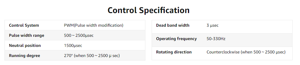
Managed to find the control signal specs. What are the PWM signals on the Duex able to supply?
-
@jrcl said in Servo Configuration Check:
@fcwilt I don't unfortunately. I'm no electrical engineer, but could I use some sort of amplification module on the signal? Not sure if PWM signals work like that/or can be amplified like that.
A PWM signal as used to drive a servo is a fixed frequency, typically 50 Hz, with a varying duty cycle.
While you could possible hear via an audio amplifier with suitable frequency range it wouldn't tell you if the signal met the needs of your servo.
You can get a fairly nice combo multimeter and oscilloscope which would do the job for $100 off of Amazon. A useful tool for working on 3D printers.
Frederick
-
@jrcl said in Servo Configuration Check:
@phaedrux Tried without the ! and here is my wiring diagram and circled the pin on the duex to be safe. Still no dice.
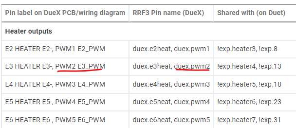
You've circled the PWM3 header, but the command you posted was for PWM2 M950 S1 C"!duex.pwm2"
Which is it?
Assuming it matches and it was just a typo, does the servo make any noise or get warm when you try and activate it?
Can you send M950 S1 by itself and report back the reply?
Can you try with some different PWM frequencies by adding a Q parameter to the M950 command?
M950 S1 C"!duex.pwm2" Q50 perhaps
-
Can you post the manufacturer and part number for your 24-to-5 Volt converter?
SeemeCNC Rostock Max V3 converted to V3.2 with a Duet2 Ethernet Firmware 3.2 and SE300
-
@phaedrux Are they not grouped like this? I figured it was just a naming convention for the pin (E3_PWM) went with the PWM number (PWM2) and I saw this on the pin name table too and thought I still called
C"duex.pwm2"though the control pin is called E3_PWM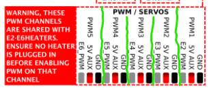
-
@alankilian Tobsun EA75-5V
-
I can't tell if that's isolated or not.
If you've got everything else figured out, try connecting the two grounds together at the converter.
-
@alankilian said in Servo Configuration Check:
I can't tell if that's isolated or not.
If you've got everything else figured out, try connecting the two grounds together at the converter.
Without knowing how the unit is designed that might be unwise.
Frederick
Printers: a E3D MS/TC setup and a RatRig Hybrid. Using Duet 3 hardware running 3.4.6
-
@fcwilt Agreed, it's a buck converter if that makes any difference, but it does seem like that would allow the full power load to pass through the Duex and potentially fry the rail. Ordering the recommended MG995, from the servo wiki, to test against at least for now.
-
@jrcl said in Servo Configuration Check:
@fcwilt Agreed, it's a buck converter if that makes any difference, but it does seem like that would allow the full power load to pass through the Duex and potentially fry the rail. Ordering the recommended MG995, from the servo wiki, to test against at least for now.
It could be fine, it could be destructive - without word from the manufacturer you just don't know.
Since it seems you have no test equipment even the lack of destruction would not insure it was actually working - it might just shutdown if wired incorrectly.
I went ahead and ordered one. I should be able to determine if the output is isolated. If so you would need to connect the grounds together. I will let you know what I find.
Frederick
-
@fcwilt You're too kind, appreciate the above and beyond support on this
-
@jrcl said in Servo Configuration Check:
@fcwilt You're too kind, appreciate the above and beyond support on this
Glad to be of help when I can.
Frederick
-
@fcwilt said in Servo Configuration Check:
@alankilian said in Servo Configuration Check:
I can't tell if that's isolated or not.
If you've got everything else figured out, try connecting the two grounds together at the converter.
Without knowing how the unit is designed that might be unwise.
@JRCL
It's perfectly safe to connect the grounds together on an isolated-output converter.
It just makes it into a nonisolated converter.Ref: (A poor reference, but nonetheless) https://electronics.stackexchange.com/questions/35800/should-i-isolate-grounds-of-an-isolated-dc-dc-converter
-
@alankilian ohhhh I see I thought you meant to use the onboard ground but positive off the converter. I will give this a try then. Redoing all the wiring on the servo too to be safe too