Issues with pressure advance since RRF 3.4
-
Since 3.4 I'm having issues with pressure advance and bulging corners.
Usually my PA value for PLA is at 0.06.Below are two test prints. With the same settings. Upper test print is RRF 3.3 and other is RRF 3.4. PA value 0.06 and no enabled input shaping.
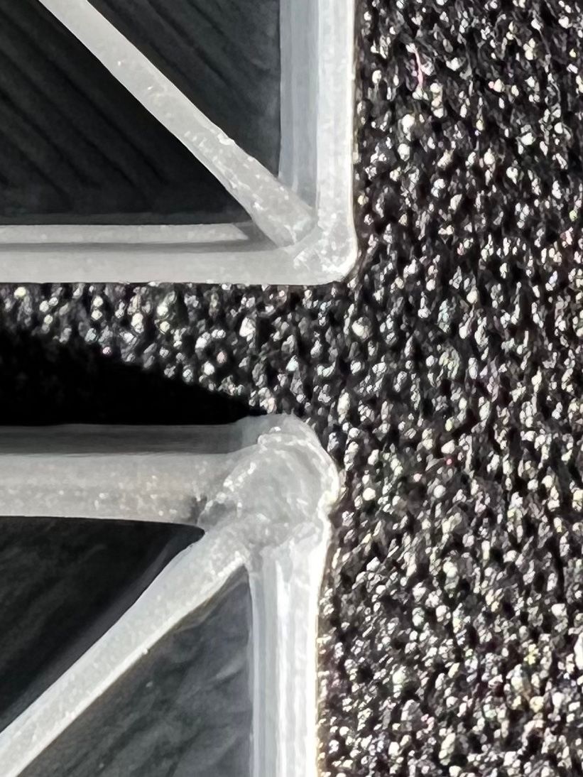
To get the same result with RRF 3.4 I would need to drastically increase PA to around 0.1 which then causes other problems (e.g. infill lines do not connect to perimeter anymore).
What might be the issue and how can I fix this?
-
@argo 3.4.0 or 3.4.1?
-
@argo Can you share your config.g file as well?
-
Here's my config:
G4 S1        ; wait 1s for expansion boards to start

; General preferences
G90                                         ; Send absolute coordinates...
M83                                         ; ...but relative extruder moves

; Network
M550 P"Walross"                        	; Set machine name
M552 S1                                     	; Enable network
;*** Access point is configured manually via M587
M586 P0 S1                                  ; Enable HTTP
M586 P1 S1                                  ; Disable FTP
M586 P2 S1                                  ; Disable Telnet
M575 P1 S1 B57600							; Panel Due

; Printer geometry
M669 K1                	                    ; Select CoreXY mode
M208 X0:290 Y-3:300 Z-0.2:270              ; Axis Limits
M564 H0							            ; allow unhomed movement

;------- drives from top---------------------------------------------------
;  B -------+------ A
;   | P.02 | P.03 |
;   -------+-------  Z-Drives
;   | P0.1 | P0.4 |
;   -------+-------
;        Front

; Drive Mappings
M569 P121.0 S0 D2                             ; Drive 0: E Axis
M569 P0.1 S1 D2                             ; Drive 1: Z-LeftFront Axis
M569 P0.2 S0 D2                             ; Drive 2: Z-LeftRear Axis
M569 P0.3 S1 D2                             ; Drive 3: Z-RightRear Axis
M569 P0.4 S0 D2                             ; Drive 4: Z-RightFront Axis
M569 P0.5 S1 D2                             ; Drive 5: Expansion: B motor (X-axis)
M569 P0.6 S0 D2                             ; Drive 6: Expansion: A motor (Y-axis)


; Motor remapping for dual Z and axis Limits
M584 X5 Y6 Z1:2:3:4 E121.0                              ; Motor mapping
M671 X-60:-60:360:360 Y-10:370:370:-10 S20	        ; Z leadscrews positions Left Front - Let Rear - Right Rear - Right Front

; Microstepping and Speed
M350 X32 Y32 E16 Z32 I1                     ; Configure microstepping with interpolation
M92 X160.00 Y160.00 Z800.00 E400.00         ; Set steps per mm	1.8 motors

; Speeds, Acceleration and Jerk
M566 X300.00 Y300.00 Z25.00 E400.00 P1          ; Set maximum instantaneous speed changes (mm/min)
M203 X24000.00 Y24000.00 Z900.00 E1200.00       ; Set maximum speeds (mm/min) ; SpreadCycle
M201 X5000.00 Y5000.00 Z1000.00 E5500.00        ; Set accelerations (mm/s^2) ; SpreadCycle

; Motor currents
M906 X1250.00 Y1250.00 Z1100.00 E700.00 I55        ; Set motor currents (mA) and motor idle factor in percent
M84 S30                                            ; Set idle timeout

; Endstops for each Axis
M574 X2 S1 P"io1.in" 					 	; Set X endstop controlled by switch
M574 Y2 S1 P"io2.in"                      	; Set Y endstop controlled by switch
M574 Z1 S2                                  ; Set endstops controlled by probe "OLD" VINDA
;M574 Z1 S1 P"io6.in"						; Z endstop switch

; Stallgaurd Sensitivy (maybe use to pause print after crash)
M915 X S2 F0 H200 R0		                ; Set X axis Sensitivity  1.8 motors
M915 Y S2 F0 H200 R0		                ; Set y axis Sensitivity  1.8 motors

; Input Shaper and Accelerometer
M955 P121.0 I05 ;Accelerometer
;M593 P"zvdd" F46 S0.05

; Z-Probe
M558 P8 C"121.io2.in" I1 H2 F250:100 T6000 A500 S0.0025	; VINDA

; Mesh Grid
M557 X5:260 Y30:250 P7                         ;

; Z Probe Offset (Probe behind Afterburner)
;G31 P1000 X0 Y25 Z1.095	; VINDA - 3Djake Nano
G31 P1000 X0 Y25 Z0.770		; VINDA - 3DSWay Textured


; Filament Runout sensor
M591 D0 P3 L25.95 E3 R10:250 C"121.io1.in" S1		 		; Filament Sensor

; Heatbed Heaters and Thermistor Bed
M308 S0 P"temp0" Y"thermistor" T100000 B4725 C7.060000e-8       ; Heatbed Thermistor
M950 H0 C"out0" T0 Q10					                        ; Creates Bed Heater (SSR)
M307 H0 R0.889 K0.762:0.000 D3.02 E1.35 S0.6 B0
M140 H0										                    ; Bed uses Heater 0
M143 H0 S116                                                    ; Set temperature limit for heater 0 to 115C Bed

; HotEnd Heaters and Thermistor HotEnd
M308 S1 P"121.temp0" Y"thermistor" T100000 B4725 C7.06e-8     	; define E0 temperature sensor
M950 H1 C"121.out0" T1 Q100					                            ; Create HotEnd Heater
M307 H1 R4.568 K0.683:0.000 D4.04 E1.35 S1.00 B0 V24.4				; PID as heater
M143 H1 S295                                                    	; Set temperature limit for heater 1 to 285C HotEnd
M302 S15 R15														; min extrusion (cold extrusion) temp

; Fans Hotend + Part
M950 F3 C"121.out1" Q100				; Creates HOTEND Fan
M106 P3 T65 L1.0 X1.0 H1                 ; HOTEND Fan Settings
M950 F0 C"121.out2" Q100				; Creates PARTS COOLING FAN
M106 P0 H-1                         ; Parts Cooling Fan

; Fans Electronic compartment & Exhaust
M950 F1 C"out3" Q100				    ; Creates Case Fan 1
M106 P1 T40 S170 L170 X170 H0                 ; Case Fan 1 Settings
M950 F2 C"out4" Q100				    ; Creates Case Fan 2
M106 P2 T40 S170 L170 X170  H0                  ; Case Fan 2 Settings
M950 F5 C"out5" Q100				    ; Creates Exhaust Fan
M106 P5 T82 S150 L150 X150 H0                  ; Exhaust fan

; Chamber Thermistor
M308 S3 P"temp1" A"Chamber" Y"thermistor" T100000 B4725 C7.060000e-8     	; define chamber sensor

; Tools
M563 P0 D0 H1 F0                            ; Define tool 0
G10 P0 X0 Y0 Z0                             ; Set tool 0 axis offsets
G10 P0 R0 S0                                ; Set initial tool 0 active and standby temperatures to 0C
@ikarisan
RRF 3.4.1 and 3.4.0 behave the same but the test above was with RRF 3.4.1 and RRF 3.3. -
Do you know if this could be firmware related or am I missing something that has changed since RRF 3.4 and I need to alter some settings?
-
@argo said in Issues with pressure advance since RRF 3.4:
Do you know if this could be firmware related or am I missing something that has changed since RRF 3.4 and I need to alter some settings?
It's possible that it is firmware related with the recent changes for input shaping, etc. Trying to identify the firmware version that causes the issues to appear and the setting used would be helpful.
-
For me the issues appeared since RRF 3.4 beta 7 (maybe also before but that was when I started to test the beta) for which I also created a thread but without real answer wether or not it's a error on my side or firmware related: https://forum.duet3d.com/topic/26062/3-4-0beta7-new-input-shaper-disturb-pressure-advance
So I'm also having issues with bulging corners with RRF 3.4 final and RRF 3.4.1.
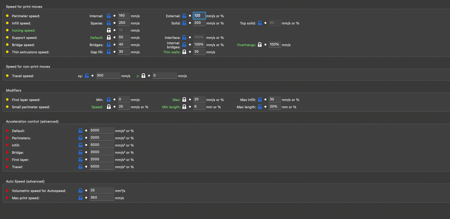
I'm using those speed / acceleration settings:
-
@argo thanks for reporting this. The implementation of PA had to be largely rewritten in RRF 3.4, so a bug may have crept in.
You said that for you, the problem started at RRF 3.4beta7. Can you remember what was the last RRF 3.4beta you installed that did not have the problem - was it beta6, or an earlier one?
Duet WiFi hardware designer and firmware engineer
Please do not ask me for Duet support via PM or email, use the forum
http://www.escher3d.com, https://miscsolutions.wordpress.com -
I just flashed RRF 3.4 beta 2 as this is the first beta that mentions input shaping and I assume PA has been rewritten for input shaping.
Here is the result. PLA, direct extruder (Bondtech LGX) and PA value of 0.068 which is already too high for direct extruder printing PLA in my opinion as you can see in the example below, the infill line is too thin at the end. But the corners are still bulging. It almost looks like PA isn't applied at all for corners compared to RRF 3.3.
Input shaping was off (for all tests in this thread).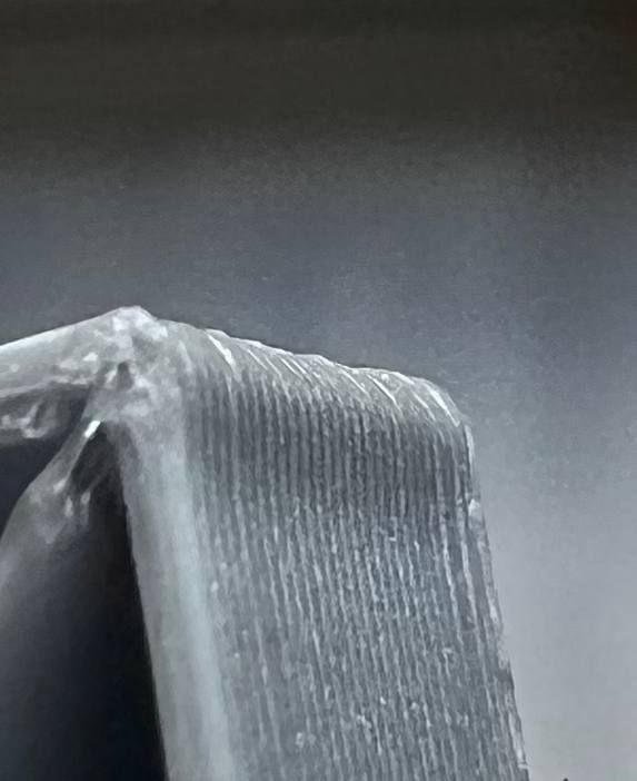
M122 right after the test print:
M122
=== Diagnostics ===
RepRapFirmware for Duet 3 Mini 5+ version 3.4.0beta2 (2021-08-03 12:43:05) running on Duet 3 Mini5plus WiFi (standalone mode)
Board ID: W0DS5-R296U-D65J0-40KM6-LU03Z-Z3F72
Used output buffers: 6 of 40 (40 max)
=== RTOS ===
Static ram: 102724
Dynamic ram: 107996 of which 16 recycled
Never used RAM 27832, free system stack 118 words
Tasks: NETWORK(ready,10.6%,214) HEAT(delaying,0.0%,343) Move(notifyWait,0.0%,255) CanReceiv(notifyWait,0.0%,773) CanSender(notifyWait,0.0%,369) CanClock(delaying,0.0%,347) TMC(delaying,1.2%,72) MAIN(running,87.3%,432) IDLE(ready,0.0%,29) AIN(delaying,0.8%,264), total 100.0%
Owned mutexes: WiFi(NETWORK)
=== Platform ===
Last reset 00:27:44 ago, cause: power up
Last software reset at 2022-07-07 15:54, reason: User, GCodes spinning, available RAM 31492, slot 1
Software reset code 0x0003 HFSR 0x00000000 CFSR 0x00000000 ICSR 0x00000000 BFAR 0xe000ed38 SP 0x00000000 Task MAIN Freestk 0 n/a
Error status: 0x04
Aux0 errors 0,0,0
MCU revision 3, ADC conversions started 1664433, completed 1664432, timed out 0, errs 0
Step timer max interval 725
MCU temperature: min 39.3, current 39.3, max 39.6
Supply voltage: min 24.4, current 24.5, max 24.5, under voltage events: 0, over voltage events: 0, power good: yes
Heap OK, handles allocated/used 99/1, heap memory allocated/used/recyclable 2048/144/132, gc cycles 0
Driver 0: position 90080, standstill, SG min/max 0/0, read errors 0, write errors 0, ifcnt 9, reads 54, writes 0, timeouts 0, DMA errors 0
Driver 1: position 1120, standstill, SG min/max 2/2, read errors 0, write errors 0, ifcnt 27, reads 54, writes 0, timeouts 0, DMA errors 0
Driver 2: position 16852, standstill, SG min/max 2/2, read errors 0, write errors 0, ifcnt 27, reads 54, writes 0, timeouts 0, DMA errors 0
Driver 3: position 0, standstill, SG min/max 2/2, read errors 0, write errors 0, ifcnt 28, reads 54, writes 0, timeouts 0, DMA errors 0
Driver 4: position 0, standstill, SG min/max 0/0, read errors 0, write errors 0, ifcnt 27, reads 54, writes 0, timeouts 0, DMA errors 0
Driver 5: position 0, standstill, SG min/max 2/2, read errors 0, write errors 0, ifcnt 27, reads 54, writes 0, timeouts 0, DMA errors 0
Driver 6: position 0, standstill, SG min/max 2/2, read errors 0, write errors 0, ifcnt 27, reads 54, writes 0, timeouts 0, DMA errors 0
Date/time: 2022-07-07 16:27:48
Cache data hit count 3022789118
Slowest loop: 3.08ms; fastest: 0.12ms
=== Storage ===
Free file entries: 10
SD card 0 detected, interface speed: 22.5MBytes/sec
SD card longest read time 0.0ms, write time 0.0ms, max retries 0
=== Move ===
DMs created 83, segments created 12, maxWait 0ms, bed compensation in use: mesh, comp offset 0.000
=== MainDDARing ===
Scheduled moves 3313, completed moves 3313, hiccups 0, stepErrors 0, LaErrors 0, Underruns [0, 0, 0], CDDA state -1
=== AuxDDARing ===
Scheduled moves 0, completed moves 0, hiccups 0, stepErrors 0, LaErrors 0, Underruns [0, 0, 0], CDDA state -1
=== Heat ===
Bed heaters = 0 -1, chamberHeaters = -1 -1
Heater 0 is on, I-accum = 0.2
Heater 1 is on, I-accum = 0.0
=== GCodes ===
Segments left: 0
Movement lock held by null
HTTP is idle in state(s) 0
Telnet is idle in state(s) 0
File is idle in state(s) 0
USB is idle in state(s) 0
Aux is idle in state(s) 0
Trigger is idle in state(s) 0
Queue is idle in state(s) 0
LCD is idle in state(s) 0
SBC is idle in state(s) 0
Daemon is idle in state(s) 0
Aux2 is idle in state(s) 0
Autopause is idle in state(s) 0
Code queue is empty
=== Filament sensors ===
Extruder 0: no data received
=== CAN ===
Messages queued 5, received 6, lost 0, longest wait 0ms for reply type 0, peak Tx sync delay 3, free buffers 17 (min 17), ts 3/3/0
Tx timeouts 0,0,0,0,0,0
=== Network ===
Slowest loop: 201.07ms; fastest: 0.06ms
Responder states: HTTP(0) HTTP(0) HTTP(0) HTTP(0) FTP(0) Telnet(0), 0 sessions
HTTP sessions: 1 of 8
- WiFi -
Network state is active
WiFi module is connected to access point
Failed messages: pending 0, notready 0, noresp 19
WiFi firmware version 1.26
WiFi MAC address f0:08:d1:02:e7:b3
WiFi Vcc 3.36, reset reason Power up
WiFi flash size 2097152, free heap 24936
WiFi IP address 192.168.1.120
WiFi signal strength -72dBm, mode 802.11n, reconnections 0, sleep mode modem
Clock register 00002002
Socket states: 0 0 0 0 0 0 0 0
Duet 1LC:
M122 B121 Diagnostics for board 121: Duet TOOL1LC firmware version 3.4.0beta2 (2021-08-03 10:00:09) Bootloader ID: SAMC21 bootloader version 2.3 (2021-01-26b1) Never used RAM 2204, free system stack 2719 words Tasks: Move(notifyWait,0.0%,99) HEAT(delaying,0.2%,105) CanAsync(notifyWait,0.0%,57) CanRecv(notifyWait,0.1%,74) CanClock(notifyWait,0.0%,65) ACCEL(notifyWait,0.0%,61) TMC(delaying,2.8%,57) MAIN(running,91.9%,352) IDLE(ready,0.0%,27) AIN(delaying,4.9%,142), total 100.0% Last reset 00:27:40 ago, cause: power up Last software reset time unknown, reason: AssertionFailed, available RAM 3392, slot 0 Software reset code 0x0120 ICSR 0x00000000 SP 0x2000415c Task Freestk 129 bad marker Stack: 00000544 00022ffc 00019b65 20003134 00016cff 20003134 000163d1 20000ed0 00000000 00000001 00008275 200071c8 200071c8 200071e0 00000000 20000f50 00011647 000223b8 00022474 00021ac8 00019b05 200071c8 200071c8 20000f50 000083ed 200071d8 000009c7 Driver 0: position 500392, 400.0 steps/mm, standstill, SG min/max 2/2, read errors 0, write errors 0, ifcnt 13, reads 386, writes 0, timeouts 0, DMA errors 0, steps req 0 done 0 Moves scheduled 2364, completed 2364, in progress 0, hiccups 0, step errors 0, maxPrep 0, maxOverdue 0, maxInc 0, mcErrs 0, gcmErrs 0 Peak sync jitter -1/4, peak Rx sync delay 183, resyncs 0/0, no step interrupt scheduled VIN: 24.2V MCU temperature: min 34.4C, current 46.0C, max 46.6C Ticks since heat task active 49, ADC conversions started 1659491, completed 1659489, timed out 0, errs 0 Last sensors broadcast 0x00000002 found 1 54 ticks ago, loop time 0 CAN messages queued 47, send timeouts 0, received 15, lost 0, free buffers 37, min 37, error reg 0 dup 0, oos 0/0/0/0, bm 0, wbm 0, rxMotionDelay 0 Accelerometer detected: yes, status: 00 I2C bus errors 0, naks 0, other errors 0 === Filament sensors === Interrupt 4 to 8us, poll 9 to 177us Driver 0: pos 339.61, errs: frame 0 parity 0 ovrun 0 pol 0 ovdue 0 -
I will add a little comment here based on my past experience tunning PA: it works very well whilw the requested speed ks close to the real speed. The further you go and the results starts to be less effective. In yor slicer config i can see a perimeter speed of 120mm s, and your infill has 260 mm s. In your pictures i see what it looks like a test cube .
If that cube is small, you will never reach 120, that would be the requested speed. Firmware will give so ething smaller.
But later in tbe infill the requested 260 speed will never be reached either but the difference between requeste and real speed will be muuuuuch bigger, so probably you wont bave very good results.
I would suggest to retune PA with a model that let you reach real values closer to the requested speed and retest to see if there is any difference -
I have same kind of issues since 3.4.
Maybe the Pressure Advance don't have a 3rd order compensation for speed variation, could be a good update.
Made 4 measurements at different speed, make the equation in excel.
Can we add this with "Duet programming Gcode" ? -
Thanks for your theory but requested speeds are reached.
-
This is very interesting. I had noticed some of these artifacts too but hadn't pinned it down to PA changes in the 3.4 releases. Good job zeroing in on this!
-
same experience, lurking for update
-
Well, that sucked... I tried to downgrade to 3.3 for a back to back print test and that almost destroyed my Mosquito hot end. The hot end fan spooled up with its normal blip, but then slowly wound down to zero at my normal PWM setting. The entire heat sink ended up packed with molten filament and had to be drilled out. The hot end fan won't stay running at any other PWM value than 255.
Off topic, but what changed between 3.3 and 3.4 on this? I'm back on 3.4 and it runs fine again.
-
@ccs86 How did you have it configured?
When a fan is configured as thermostatic using M106, the S parameter is now ignored. If a single T value is given, then when the temperature is above the T parameter the fan will run at the PWM specified by the X (maximum PWM) parameter (default 1.0).
From the 3.4 notes.
-
Could you also please provide some examples? So we can be sure we are having the same issue.
-
-
@phaedrux said in Issues with pressure advance since RRF 3.4:
@ccs86 How did you have it configured?
When a fan is configured as thermostatic using M106, the S parameter is now ignored. If a single T value is given, then when the temperature is above the T parameter the fan will run at the PWM specified by the X (maximum PWM) parameter (default 1.0).
From the 3.4 notes.
Apologies for going off topic, but by that statement M106 in GCode dictionary could very much do with a rewrite
")
-
@gnydick Can I just check, I think in the your other thread you reported that going back to 3.3 did not make any difference to the results you are seeing? Is that correct or was the regression test you did just to 3.4?