Mesh bed compensation issue
-
@norder and @rogerpodacter after correcting the Y rail alignment the heightmap looks pretty good. No more slope on hte left side.
But my first layer is still not perfect especially on the left side.

Maybe now it is really the BL touch?
-
I think you have a little misconception here.
The super result of @rogerpodacter on his heihtmap, that everything is very flat there and one corner of yours turns red, simply has to do with the fact that @rogerpodacter's printing surface has no bumps or is bent, yours seems to be a little bent in one corner .
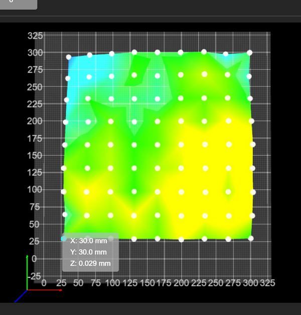
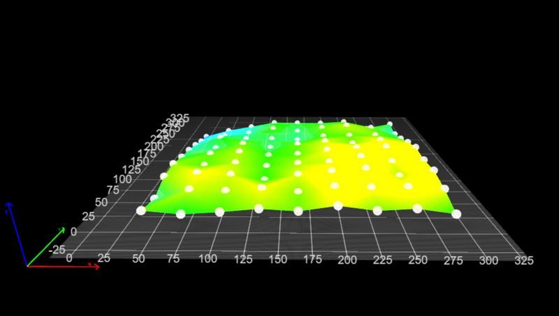
Mine too, by the way.This is how my heihgtmap looks like with the IR probe.
The manual leveling was done, which the G32 command does automatically for you.
After that an MBL was made with G29.
My first layer of 0.1mm across the entire print bed would be perfectly even.The heihgtmap shows the unevenness of the pressure plate somewhat exaggerated. The differences are hardly bigger than a hair is thick. My FR4 pressure plate is as smooth as a mirror when you look at it.
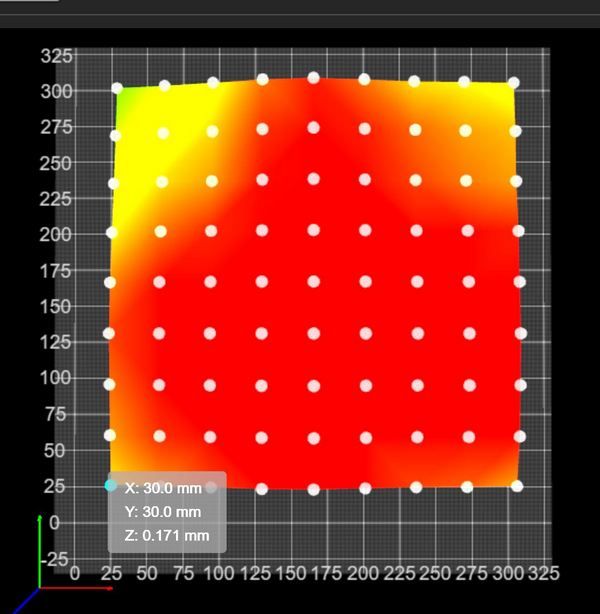
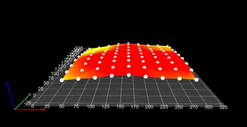
Here is a heightmap with the BLTouch where I haven't done the manual leveling yet, you can see everything is red and I was also warned that the MBL cannot compensate for this extreme difference, I should level the print bed manually first.
You can also see that both probes have the same measuring points with me.
All around is an area of 30mm that is not measured because the BLTouch doesn't quite reach the right edge.
It is not important that both probes have the same measuring points, I just wanted it to be identical and it makes it easier for me to compare the two probes to each other.
So not important for you.
.
.
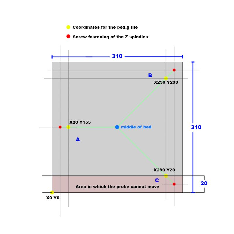
But this plan is important for you after I have calculated my level points.
In your case it would be the coordinates in your bed.g file.
So what is manual leveling for me is the bed.g file for you, which you call up with the G32 command.My level screws (red dots) are 10mm from the edge but my BLTouch can only get up to 30mm on one side of the print bed.
Shown in the sketch as a somewhat reddish area, here it is given as 20mm and in the lower area of the print bed.
But that doesn't matter because you have to determine beforehand where your probe goes and where it doesn't go.
Often it's an area on the print bed... right edge, left edge, top or bottom depending on where your probe is mounted on the print head.Now you have to draw a line from each mounting point of the spindles (red dots) to the middle of the print bed (green lines).
Then calculate the area where the probe cannot reach.
And with these measurements you can calculate where the coordinates for the bed.g file are (yellow dots).
They must be on the green line and all the same distance from the attachment point.I saw that your axis limits are not quite OK.
At minimal you have a positive value (X2).
M208 X2 Y-40 Z0 S1 ; set axis minimumAnd at maximum you have a value that is smaller than the actual print bed (Y303).
M208 X320 Y303 Z300 S0 ; set axis maximaTopic G32 + G30..
Yes, sometimes it is a bit confusing whether the offset values of the probe are taken into account or whether you have to do it yourself.
If you enter G30 without coordinates, then the probe measures where the print head is currently located.
If it is to be a specific point that is to be measured, such as X20 Y30, then you have to go there beforehand with G1 and calculate the offset yourself, i.e. G1 X78 Y30.
Your new probe offsets are included here.If you enter G30 P0 X20 Y30 Z-99999 as in the bed.g file, then the probe will measure exactly at the point, the offset of the probe will be automatically taken into account.
So enter the coordinates in bed.g that you would calculate with such a sketch, you don't have to consider the offset of the probe.
Phew... written a lot.
I hope Google doesn't translate it into cryptic and it helps you get there.
Conclusion: Not many people have such a nice, flat and uniformly green heightmap as @rogerpodacter has, which does not mean that the first layer cannot be printed absolutely perfectly.Your task in my eyes would be...
Measure the area where the BLTouch goes after the conversion, remember the M564 command I gave you in comment #15.Measure the points and coordinates from the example sketch.
Changing the axis limits in the config.g with the new insights from the M564 thingy.
So I have to vote now. Today is elected here in Germany / Lower Saxony.
I hope there will be positive changes after that.
It can't go on like this.Google Translate
-- Original Text--Ich glaube Du hast hier einen kleinen Denkfehler.
Das Super Ergebnis von @rogerpodacter seiner heihtmap das dort alles sehr plan ist und bei Dir eine Ecke ins Rot geht, hat einfach damit zu tun das die Druckoberfläche von @rogerpodacter keine Unebenheiten hat oder verbogen ist, Deine scheint in einer Ecke etwas verbogen zu sein.
Meine übrigens auch.So sieht zB meine heihgtmap mit dem IR-Probe aus.
Das manuelle Leveling wurde gemacht, was bei Dir der G32 Befehl automatisch macht.
Danach wurde ein MBL mit G29 gemacht.
Mein erster Layer mit 0,1mm über das gesamte Druckbett wäre absolut gleichmäßig.Die heihgtmap zeigt die Unebenheiten der Druckplatte etwas übertrieben dar. Die unterschiede sind kaum größer wie ein Haar dick ist. Meine FR4 Druckplatte ist so glatt wie ein Spiegel wenn man sie sich ansieht.
Hier eine heightmap mit dem BLTouch wo ich das manuelle Leveling noch nicht gemacht habe, man sieht alles ist Rot und es wurde mir auch eine Warnung angezeigt dass das MBL diesen extremen Unterschied nicht ausgleichen kann, ich möge doch erst einmal das Druckbett manuell leveln.
Du siehst auch das beide Sonden die gleichen Messpunkte bei mir haben.
Rundherum ist ein Bereich von 30mm der nicht gemessen wird, weil der BLTouch nicht ganz bis an die rechte Kante kommt.
Es ist nicht wichtig das beide Sonden den gleichen Messpunkte haben, ich wollte es nur identisch haben und es erleichtert mir etwas beim Vergleich der beiden Sonden zueinander.
Also nicht wichtig für Dich.Wichtig für Dich ist aber dieser Plan nachdem ich meine Levelpunkte ausgerechnet habe.
Es wären in Deinem Fall die Koordinaten in Deiner bed.g Datei.
Also das was bei mir das manuelle Leveln ist, ist bei Dir die bed.g Datei die Du mit dem Befehl G32 aufrufst.Meine Levelschrauben (Rote Punkte) sind 10mm vom Rand entfernt aber mein BLTouch kommt an einer Seite des Druckbettes nur bis 30mm heran.
In der Skizze als etwas rötlichen Bereich dargestellt, hier jetzt mal mit 20mm angegeben und im unteren Bereich des Druckbettes.
Aber das ist egal denn Du muss vorher feststellen wo Deine Sonde hin kommt bzw wo sie nicht hin kommt.
Oft ist es ein Bereich auf dem Druckbett... rechter Rand, linker Rand, oben oder unten, je nachdem wo Deine Sonde am Druckkopf montiert ist.Jetzt musst Du eine Linie von jedem Befestigungspunkt der Spindeln (Rote Punkte) bis zur Mitte des Druckbettes eine Linie (Grüne Linien) ziehen.
Dann den Bereich einberechnen wo die Sonde nicht hin kommt.
Und mit diesen Maßen kannst Du ausrechnen wo die Koordinaten für die bed.g Datei sind (Gelbe Punkte).
Sie müssen auf der grünen Linie sein und alle den gleichen Abstand zum Befestigungspunkt haben.Ich habe gesehen das Deine Axis Limits nicht ganz OK sind.
Bei minimal hast Du einen positiven Wert (X2).
M208 X2 Y-40 Z0 S1 ; set axis minimaUnd bei maximal hast Du einen Wert der kleiner wie das tatsächliche Druckbett ist (Y303).
M208 X320 Y303 Z300 S0 ; set axis maximaThema G32 + G30..
Ja, manchmal ist es etwas verwirren ob die Offset Werte der Sonde mit einberechent werden oder ob man es selber machen muss.
Gibst Du G30 ohne Koordinaten an, dann misst die Sonde dort wo der Druckkopf gerade steht.
Soll es ein bestimmter Punkt sein der gemessen werden soll wie zB X20 Y30, dann muss man dort vorher mit G1 hingefahren sein und das Offset selber mit berechen, also G1 X78 Y30.
Hier sind Deine neuen Offsets der Sonde mit drin.Gibst Du wie in der bed.g Datei G30 P0 X20 Y30 Z-99999 ein, dann misst die Sonde genau an dem Punkt, der Offset der Sonde wird automatisch mit einberechnet.
Also in bed.g die Koordinaten eingeben die Du mit so einer Skizze ausrechnen würdest, den Offset der Sonde musst Du nicht beachten.
Puh... viel geschrieben.
Ich hoffe Google übersetzt es nicht ins Kryptische und es hilft Dir ans Ziel zu kommen.
Fazit: So eine schöne plane und einheitlich Grüne heightmap wie @rogerpodacter er sie hat, haben nicht viele, was aber nicht bedeutet das der erste Layer nicht absolut perfekt gedruckt werden kann.Deine Aufgabe in meinen Augen, wäre...
Bereich ausmessen wohin der BLTouch nach dem Umbau überall hin kommt, denke dabei an den M564 Befehl den ich Dir in Kommentar #15 gegeben habe.Ausmessen der Punkte und Koordinaten aus der Beispiel-Skizze.
Ändern der Axis Limits in der config.g mit den neuen Erkenntnissen aus dem M564 Dingsbums.
So, ich muss nun zur Wahl. Heute wird hier in Germany / Lower Saxony gewählt.
Ich hoffe es gibt danach positive Veränderungen.
So kann das ja nicht weiter gehen. -
@norder said in Mesh bed compensation issue:
But this plan is important for you after I have calculated my level points.
At first thank you for the detailed comment again.
I have done a similar CAD drawing already in the morning the only difference was that I did not put hte G31 points onto the line pointing into the middle of the bed only the same distance from the Z axes in all 3 cases. Now I changed this according to your proposal.
This is how it looks like (I know it i sa mess just because I wanted to put all the measurements from the frame etc onto the drawing.)
The biggest rectangle is my frame (I cannot reach with the current setup the rear 5mm of the bed this is why my max Y limit is 305. I know this is stupid because I could move the complete Z assmebly 5-10mm forward and then I could reach it but I have just done some changes and I was too lazy to do this up to now ).
).
The bed is clearly the 310 x 310. Furhtermore you can see the 3 outside points (41mm from the frame on both sides ) for the 3 axis and the 3 inner points on the lines now are the probing points for the G32 (262mm is my max Y reach point on the right for the BL touch).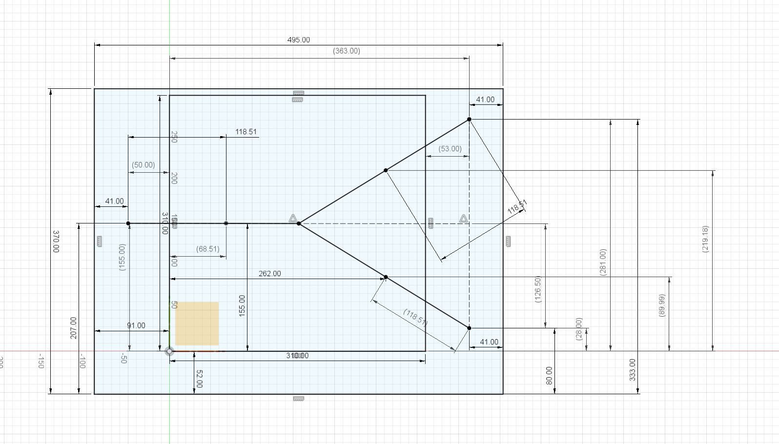
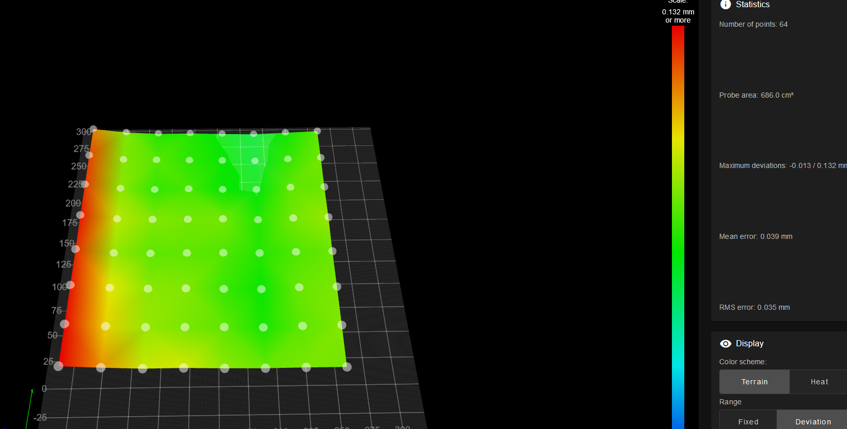
This is how my heightmap looks like with a narrow space all around (after the Y axis realignment now this is on the same level in the entire bed length but ca 0.13mm higher than the rest of teh bed.).
@norder said in Mesh bed compensation issue:
I saw that your axis limits are not quite OK.
At minimal you have a positive value (X2).
M208 X2 Y-40 Z0 S1 ; set axis minimum
And at maximum you have a value that is smaller than the actual print bed (Y303).
M208 X320 Y303 Z300 S0 ; set axis maximaAs I wrote above I am limited at 305mm at the moment because of the bed position on the actuan assembly. I will later on move the complete Z assembly forward by 10-15mm.
@norder said in Mesh bed compensation issue:
Yes, sometimes it is a bit confusing whether the offset values of the probe are taken into account or whether you have to do it yourself.
If you enter G30 without coordinates, then the probe measures where the print head is currently located.
If it is to be a specific point that is to be measured, such as X20 Y30, then you have to go there beforehand with G1 and calculate the offset yourself, i.e. G1 X78 Y30.
Your new probe offsets are included here.Yes, little bit confusing but now I already figured out which is taking into account the offset and which not. Thanks a lot

@norder said in Mesh bed compensation issue:
I hope Google doesn't translate it into cryptic and it helps you get there.
No, it was perfect. Thanks for the lots of help again

@norder said in Mesh bed compensation issue:
Not many people have such a nice, flat and uniformly green heightmap as @rogerpodacter has, which does not mean that the first layer cannot be printed absolutely perfectly
Unfortunatley not... and this is my 2nd cast alu bed for a hell amount of money.......
@norder said in Mesh bed compensation issue:
Measure the area where the BLTouch goes after the conversion, remember the M564 command I gave you in comment #15.
Measure the points and coordinates from the example sketch.
Changing the axis limits in the config.g with the new insights from the M564 thingy.I have done these all now
 I am just printing my test.
@norder said in Mesh bed compensation issue:
So I have to vote now. Today is elected here in Germany / Lower Saxony.
I hope there will be positive changes after that.
It can't go on like this.Haha
 By the way I am also living in Germany at the moment (since 4 years) but I am moving in 1,5 month
-
@kiki0000 said in Mesh bed compensation issue:
@norder it turned out perfect on the entire surface really close to the sides too. Ignore that single ca 5x5 mm spot on the fron left short piece (picture is rotate 90 deg to the right now...). All around is perfect so it was jsut some grease on the plate. It is nice to work on the print surface....

I hope it will stay like this now forever

Thank you for all the support.
-
@kiki0000 I was going to respond to your updated bed mesh, where the left side was angled sloping downwards. this to me is a very good result and shows your bed is very flat, but the left horizontal Y rail was simply out of plane with the other Y rail. Once you get symmetrical probe points, the left over is is hardware related, which one final adjustment should fix it permanently.
Then i see you mentioned something about grease, and now you have good results. I hope your bed mesh is looking good now.
-
@kiki0000
It's wonderful that the print result is now usable. The thing about the unusable area because of the offset Z assembly is annoying, but not a broken leg.
In all the years I have only used the complete print bed for one printed part, there was only a few mm of space at the edge.Oh, you live in Germany, where about?
Then you can speak German and I'll break one off here to write it in such a way that even a cryptic translation can still be understood.
Where should we go at the turn of the year (relocation)... in the south? -
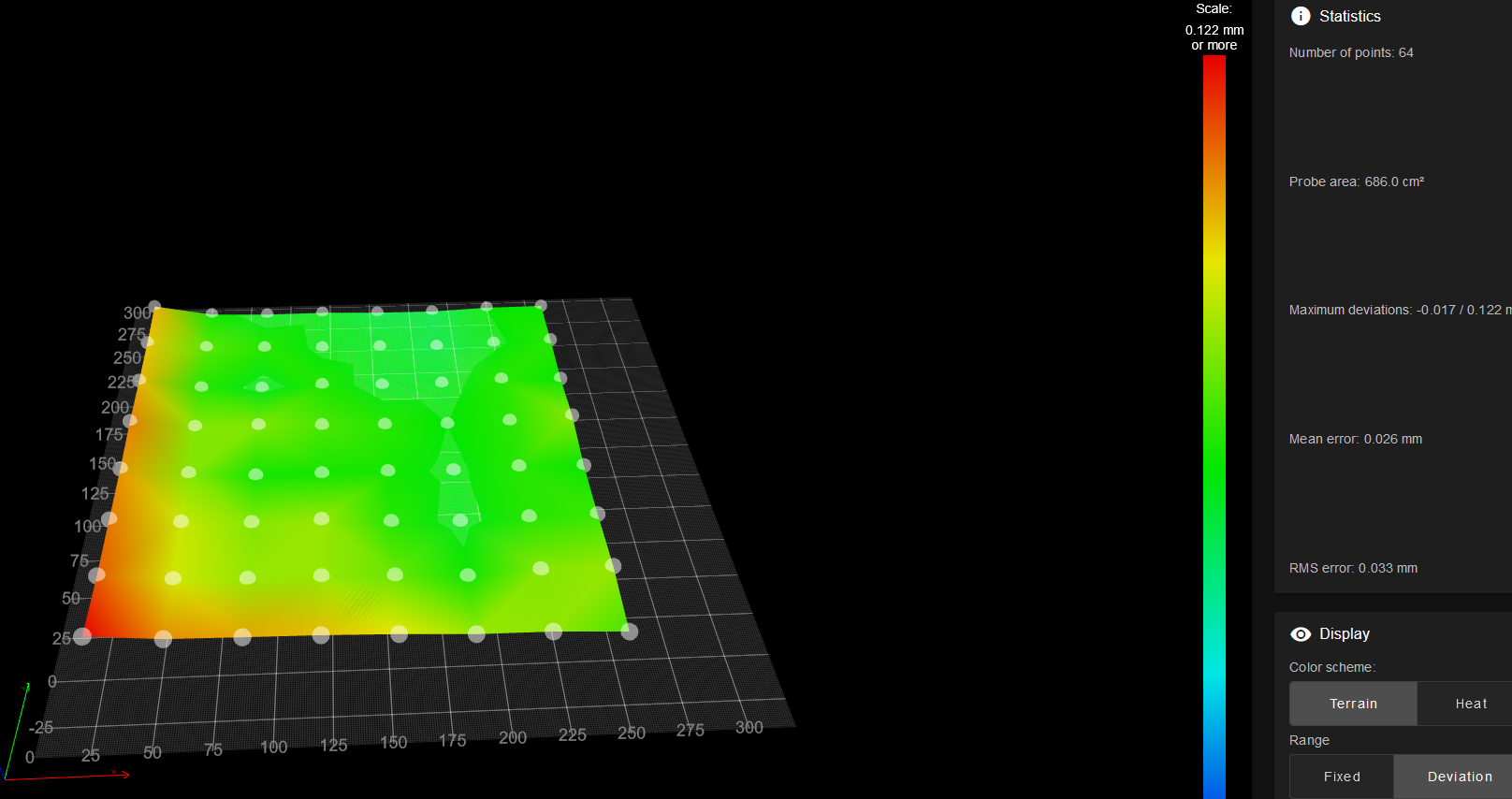
@rogerpodacter this is how my heightmap looks like. I definitely have a higher band on the left side but now it is straight and the prints look perfect.
Thank you for the support. -
@norder said in Mesh bed compensation issue:
The thing about the unusable area because of the offset Z assembly is annoying, but not a broken leg.
I could somehow make my print head smaller and putting the BL touch closer to the head. Then I would get my ca 30mm back.
@norder said in Mesh bed compensation issue:
In all the years I have only used the complete print bed for one printed part, there was only a few mm of space at the edge.
I think I have never printed full bed...
@norder said in Mesh bed compensation issue:
Oh, you live in Germany, where about?
I live in Munich.
@norder said in Mesh bed compensation issue:
Then you can speak German and I'll break one off here to write it in such a way that even a cryptic translation can still be understood.
I can speak German a little bit but English is definitely better for me.

@norder said in Mesh bed compensation issue:
Where should we go at the turn of the year (relocation)... in the south?
I am originally hungarian and we will move back there. We bought a house there (around Munich this is impossible) and now I will have a nice workshop at home (basically 2 because an electrical and a mechanical in the garage)
 I am super excited.
 -
@kiki0000
Munich... expensive patch.Hungary... very nice... when I hear Hungary I always think of lots of nature and friendly down-to-earth people who are content with what they have.
I would like to see Hungary for myself.
Who knows, if my dream of an expedition vehicle comes true, we might meet at the gas station or in the supermarket and nobody will know about the other.
-
@norder said in Mesh bed compensation issue:
would like to see Hungary for myself
I would recommend to visit lake Balaton (Plattensee) . It is really nice and huge.