SLS printer Build-Stepper galvo
-
Hello all
Mainboard: Duet 3 6HC
Im working on SLS 3d printer project, its almost complete,
I have an issue in X & Y using Nema 17 1.8'motors,
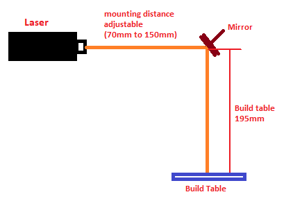
I use stepper motors to move mirrors on X&Y (both mirrors mounted directly on the motor shaft on X & Y)
my working distance is around 195mm from Y-Mirror,
So as per the steps per mm calculation, My steps per mm is 40 @ 256microstepping,
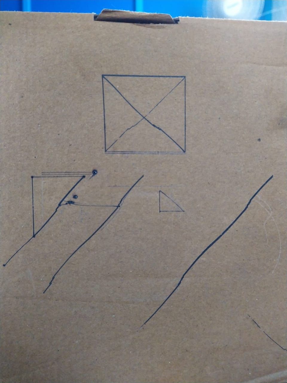
this system not working well, especially when i draw a circle it turns to oval with un even shape, i have attached some sample photos, can anyone give me idea?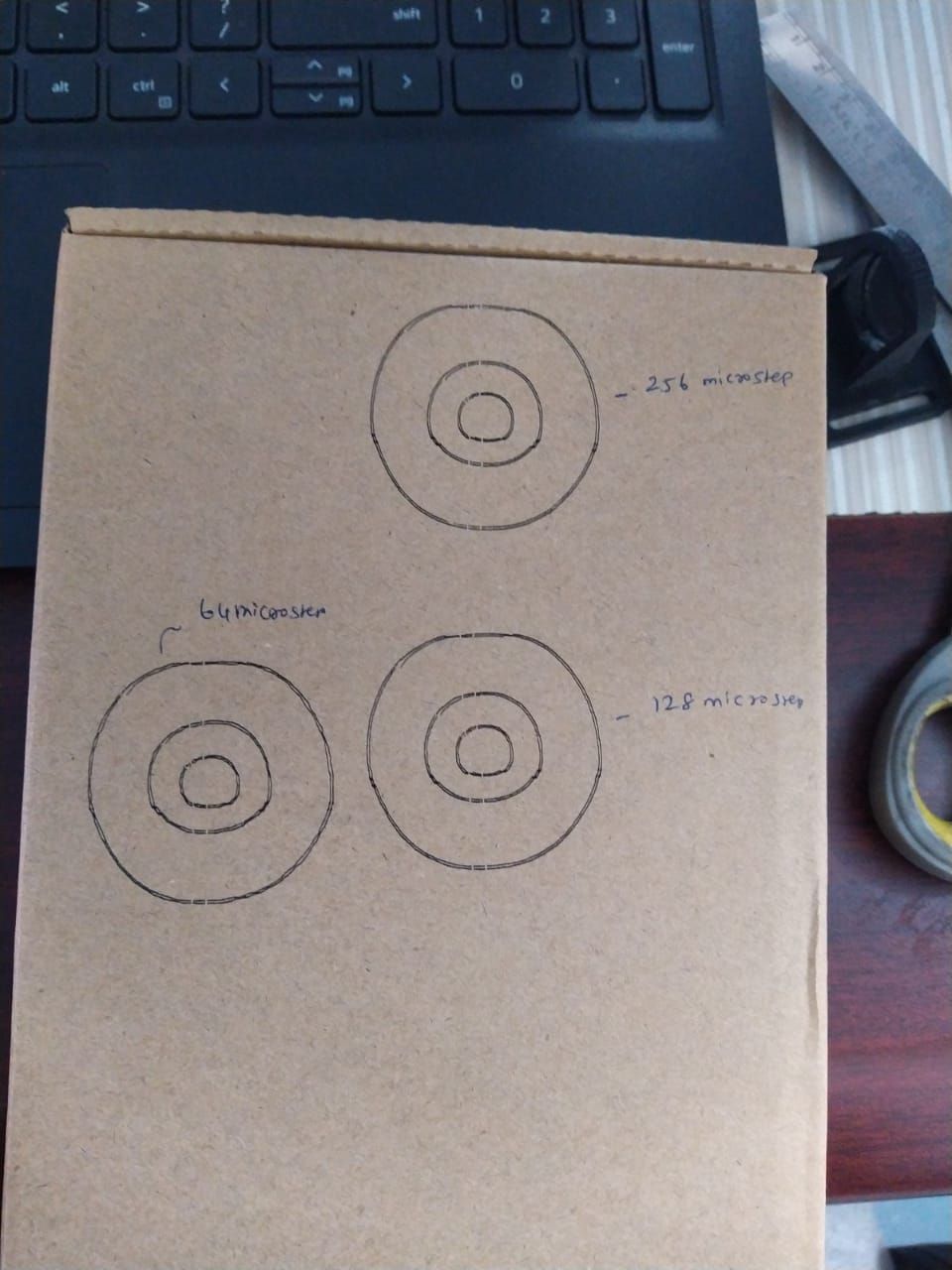
-
@adhanabal I think this HACKADAY article will explain what's going on with your setup.
Basically, you're trying to use a stepper motor to position to within 1.8/256 = 0.007 degree which is not a reasonable expectation for stepper motors.
It's why this is usually done with galvanometers and not stepper motors.
You could try the suggestions of adding a lever and a mass to load the motor in one direction, but I'm afraid you're trying to do something that's not possible.
I HOPE I'm wrong, so please don't think this is a comment meant to cause you to give up.
If you "do the math" and see how accurate your mirror angle needs to be in degrees when the LASER is within the accuracy limit you have chosen and write about that, some of the members in this forum might have additional suggestions.
Good luck, and keep up informed on your progress.
You might not want to change designs, but there are a lot of galvanometer-based LASER scanning systems available for relatively few dollars. Here's one.
SeemeCNC Rostock Max V3 converted to V3.2 with a Duet2 Ethernet Firmware 3.2 and SE300
-
@adhanabal I agree with the reply from @alankilian. If you switch to 0.9deg motors then the error should be reduced (maybe halved), but that's likely still not good enough.
Duet WiFi hardware designer and firmware engineer
Please do not ask me for Duet support via PM or email, use the forum
http://www.escher3d.com, https://miscsolutions.wordpress.com -
@alankilian @dc42
Thank you for the detailed explanation, do you know how to control the galvo mirrors through duet wifi?
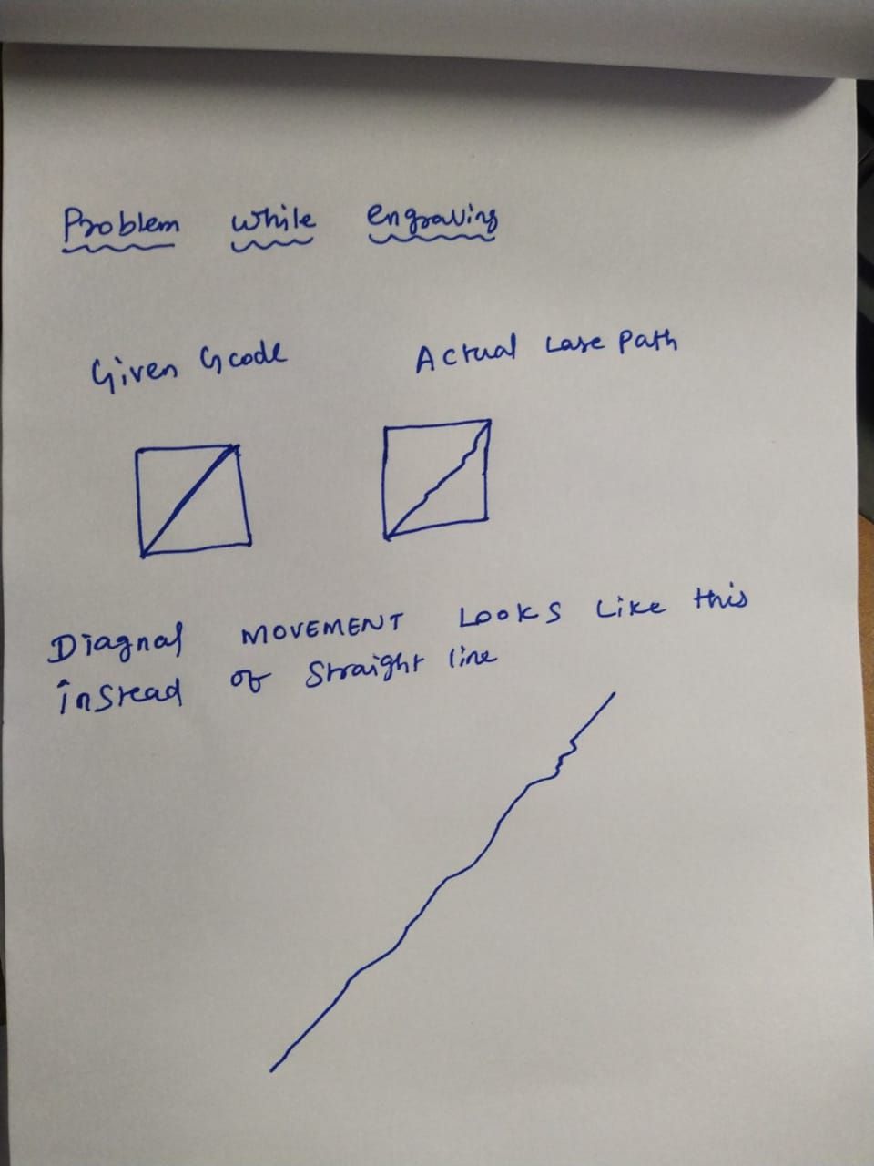
And I had an interesting problem with my stepper mirror setup.
The issue is:
I fired laser at 0 position, then gave incremental value
Of 10,20,30,and marked the spots upto 40mm,
Then I reversed the direction decremental value of 10mm from 40,30,20,10,0.
The laser spot is coming near to the spots formed earlier, actually it should come on top of it.
But the 0 position and 40mm postion are coming perfectly on the same position.

-
@adhanabal all the galvo drivers I have seen use analog inputs to control the galvo position. I would use one CPU in a RPi Pico to read the step and direction outputs from the Duet 2 expansion connector, and the other CPU to output the step count via SPI to a high resolution DAC. You will also need to be able to set the home position, which you could do by limiting the counter and having the Duet send enough step pulses to reach the limit.
Duet WiFi hardware designer and firmware engineer
Please do not ask me for Duet support via PM or email, use the forum
http://www.escher3d.com, https://miscsolutions.wordpress.com -
@dc42 thank you..will analyse that
-
@dc42
Hi what if i use closed loop stepper instead of normal steppers? will the results improve?
https://robu.in/product/makerbase-closed-loop-nema-17-servo42-motor-with-adapter-for-3d-printers-without-display-v1-1/?gclid=Cj0KCQjwteOaBhDuARIsADBqReijUELz0S-4NIP56-07A9HKJd7GbiGmyIGS5IsSdB57qSkDJv2JDrEaAtdJEALw_wcB -
@adhanabal it might help if the encoder on the motor has a very high resolution and the firmware on it is capable of achieving that level of positioning accuracy.
-
@adhanabal those particular closed steppers say the following:
precision: 0.1125 degree which is 3200 in a full rotation, the same at 16 microstepping with a 1.8 degree motor. They may be better than that because microsteps are not guaranteed to be equally spaced especially under load.
I think you need to work out what resolution of angle adjustment you need in the machine and then look for a motor that achieves that.
-
@T3P3Tony


I replaced 1.8' motor with 0.9degree stepper results improved still not enough -
@adhanabal yeah so, as i said, you need to work out what resolution angle of the motor means for the performance of the cut/raster and once you know that you can specify the motor