2 Kinematics / 1 Printer - filament arm
-
https://forum.duet3d.com/topic/17479/assign-axes-to-kinematic-multiple-kinematics
How about this threads..... Can´t I just install an arm?How about the CoreXYUV. I could not find a solution to tell the printer the turning point or base turning point of the U and V and how to define those. I mean it´s a non linear move and I ask again: Is this possible with this kinematic?
How to define a 2 axis arm? @T3P3Tony
I´m sorry but I have been thinking a lot about my filament arm. I just need software support and not 10 more physical ideas......like I also had many ideas. I tried everything without a motor on the arm by moving it by hand. It´s physycally working...
I mean it should be working to have an arm which follows the printhead, I think.
Thanks a lot
-
@IndeX4D said in 2 Kinematics / 1 Printer - filament arm:
I just need software support and not 10 more physical ideas......like I also had many ideas. I tried everything without a motor on the arm by moving it by hand. It´s physycally working...
The reason i mentioned other options for this is they already exist as kinematics in firmware. What you need is a new, custom, kinematics class to achieve your requirements and currently cant use multiple kinematics at the same time. That is unless @JoergS5 's work would generalise as far as this.
In the mean time you could potentially process the gcode so the commands for the arm movement were included in the same command as the main printer command:
e.g.
G1 Xnn Ynn Znn Ann BnnWhere the Ann and Bnn were the absolute rotations required to keep the end of the arm where you needed it for the XY positions of the main printer. That is basically doing the kinematics for this part of the system outside of the firmware.
-
@IndeX4D said in 2 Kinematics / 1 Printer - filament arm:
How about the CoreXYUV. I could not find a solution to tell the printer the turning point or base turning point of the U and V and how to define those. I mean it´s a non linear move and I ask again: Is this possible with this kinematic?
No
-
@o_lampe In v3.5 we will support independent motion systems and it will be possible to operate two independent G-code streams in SBC mode then.
In theory you can run two DSF instances on a single SBC controlling two Duets but for your proposed scenario it would still require a plugin to split up incoming codes from the main DSF instance and to send them to the second instance when necessary.
-
@deckingman said in 2 Kinematics / 1 Printer - filament arm:
The second option is to leave the axes as individual XYU and V axes but then you have to post process the sliced gcode file to generate the U and V moves. That is what I do because I prefer the UV gantry to follow the XY gantry but within an allowable tolerance. It's more complicated but allows me to (for example) position the UV gantry in the centre of a circle or other small feature where it will remain stationary while the hot end on the XY axis carries out the small moves necessary to print that feature.
I think that will be the solution.
Thank you for the script. I think that´s very helpful.
I have a friend who is data scientist so he can help me with it...... he said it´s well written!Like I told above, I think it´s gonna be the solution with the five ´´XYZAB´´ Robot.
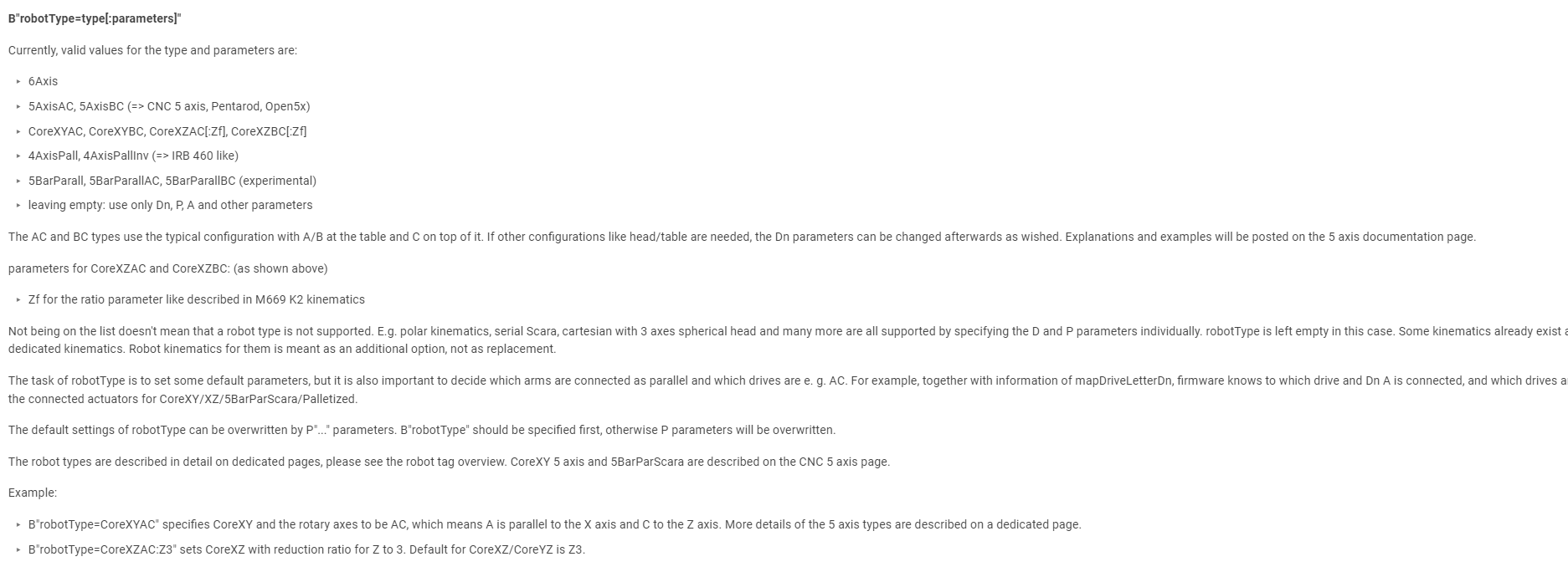
I read this https://docs.duet3d.com/User_manual/Machine_configuration/Configuring_RepRapFirmware_for_a_Robot_printer
and at the Moment I´m doing to prepare the g code.I´m not sure about robot type. I think ´´ leaving empty´´ is the right solution here?! because there is no 5 axisAB?
In the next hours and days, I´ll built my arm - then going ahead with software.
-
"Where the Ann and Bnn were the absolute rotations required to keep the end of the arm where you needed it for the XY positions of the main printer. That is basically doing the kinematics for this part of the system outside of the firmware."
To be not confused. After post-processing in cura, my g code should have A and B information, but in Angles and not in coordinates?
Example style: G1 X3.213 Y4.4 Z10 A39° B23.89° ? -
@IndeX4D yes that was my idea (except you would not add the degree signs) you would setup A and B as rotary axis and set the "steps/mm" to be "steps/degree".
-
@T3P3Tony
Ok that sounds like a good plan.
May there is somewhere a script which does exactly this? Otherwise I have to work on that..... could share it later.Drive assigment : M584 X0 Y1 Z2
M584 A3
M584 B4Is this ok when having 2 y-axis-motors`?
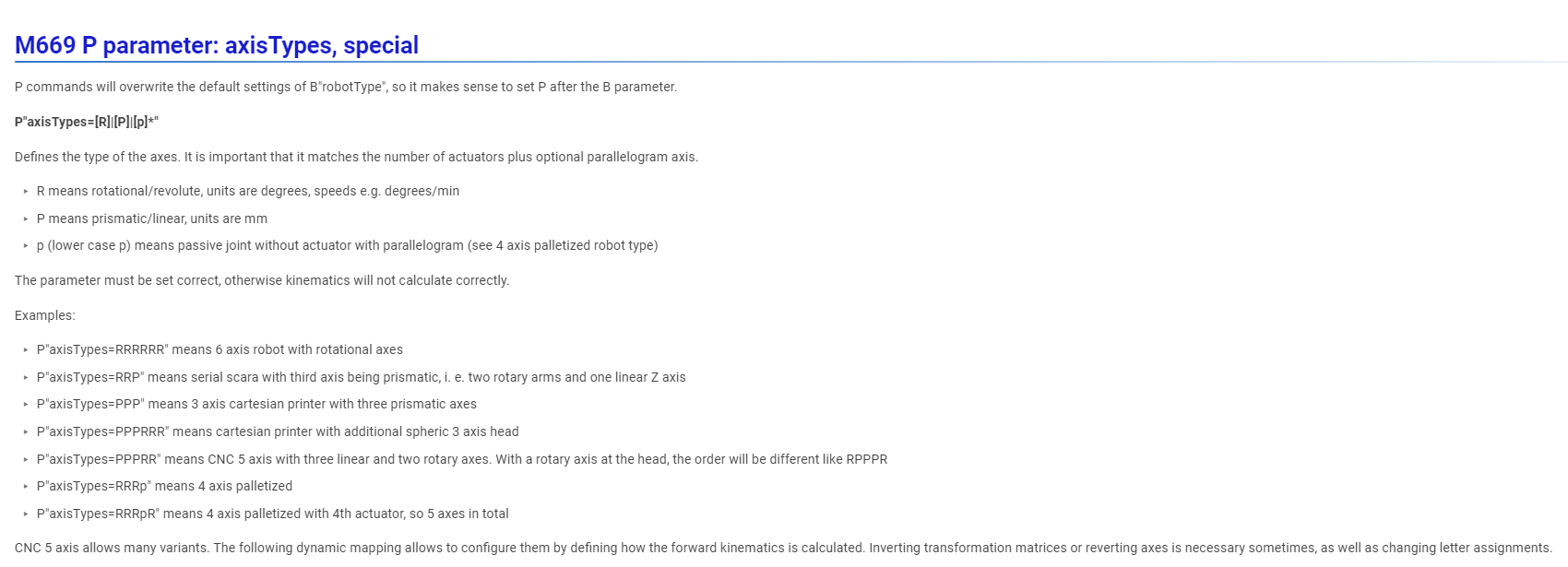
Axis type:
I guess I have to chooese --> P"axisTypes=PPPRR"
-
-
@IndeX4D I didn't follow this thread completely, so my understanding may be wrong.
If I understand correctly, you have some kinematics and want to build a separate kinematics to follow the hotend. So two independent kinematics, which are connected by the position information.
The robot kinematics creates one chain of connected actuators, so they are not independent. You will not be able to decouple them, because there is one input and one output of the chain. You need one input and this input split into two outputs.
The source to the code is mentioned on the page you mentioned above about configuration of the robot, 4th text line, github...
I am myself very interested in multi-kinematics, I wrote a thread in https://reprap.org/forum/read.php?185,824669 a long time ago, but currently my primary interest is finishing the robot kinematics.