Unable to stop severe bulging in corners with new print head
-
@deckingman I have tried printing at 240°C and the result is the same. I previously tried a print where the PA value was increased as the print got taller, by the end the value was far too high, causing the top infill to have gaps in it, but the bulging was consistent all the way from the bottom to the top.
Left is PA test. Right is 240°C test.
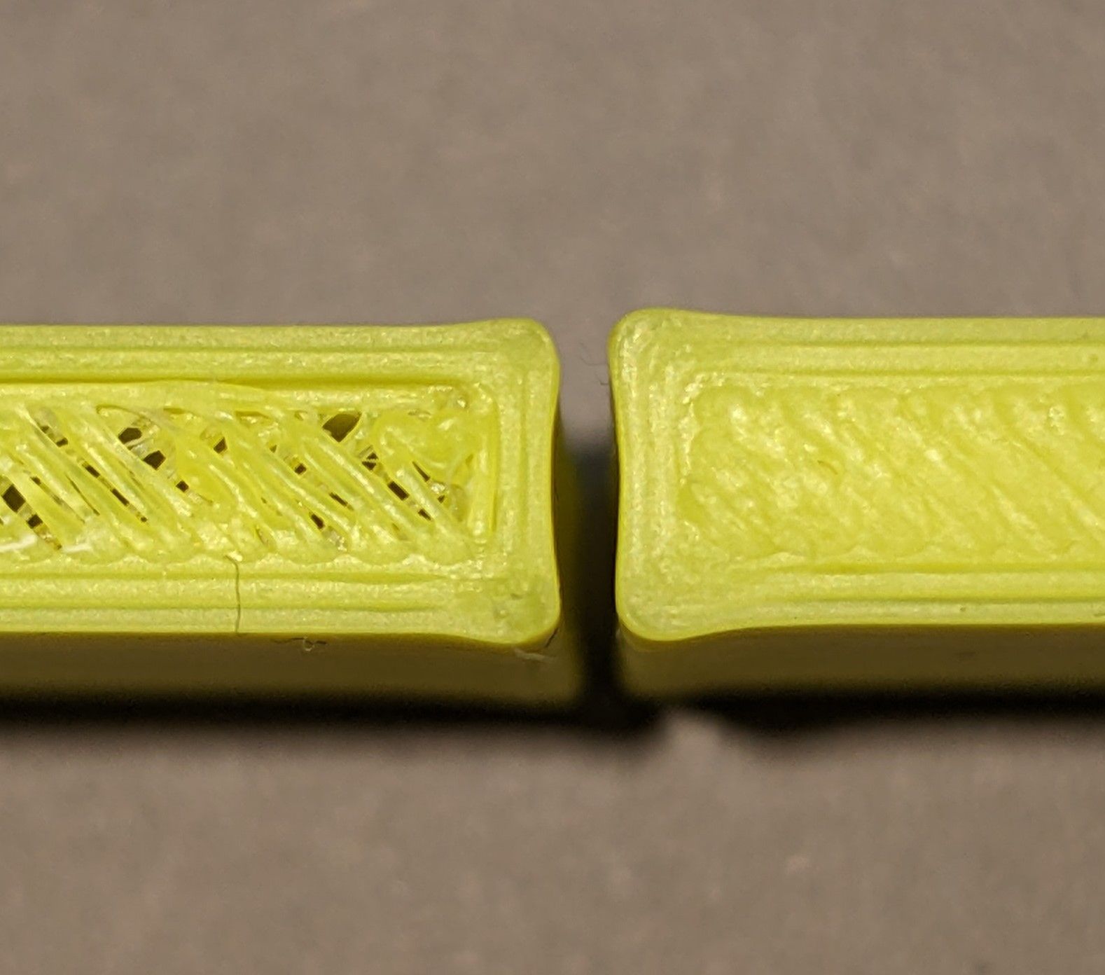
The new hotend does ooze a little more due to the longer melt zone, but I have it tuned in well enough that I don't get any stringing.
@deckingman said in Unable to stop severe bulging in corners with new print head:
bulging corners could be due to the rate of filament flow not slowing down at the end of a move at the same rate of change of the head speed, thus giving over extrusion at that point.
This is why I also tried running tests with height modifiers on extruder jerk and XY jerk, starting from far too low at 200, all the way up to far too high at 4800. These were independant tests, so the XY and E jerk values would cross over. I did a similar set of tests with acceleration on XY and E. All with no change at all in the bulging.
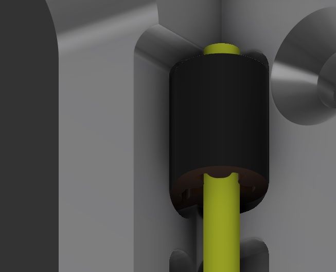
I pulled the belts tight by hand before I secured them using the method in the picture below and found before I adjusted the belt tensioners, that they were already tighter than I expected. Unfortunately, this was after I had trimmed off the excess. However, I don't think they are overly tight. They are a tiny bit tighter than before I changed the belts and print head. According to Gates, new belts should be installed at a higher tension anyway, so I imagine they will loosen up a little over time.
-
@Threepwood That's quite dramatic bulging isn't it? But the more I look at your pictures, the more I think there is more too it than just bulging corners. As I mentioned before, the hole in your first picture doesn't look anything like circular. But in your later photos, that infill is crap to put it bluntly. Are you sure you have the extruder steps per mm dialled in correctly? It looks awfully like over extrusion. Might be worth playing around with the extrusion multiplier just to see if that improves anything. But don't mess around with 1% increments - go big like 5% increments down to 80% or even less - just to see.
-
Here is another thought. Are you sure that the temperature sensor settings in your M308 match actual sensor in use? If it's a pt 1000 is that how you have M308 configured? If it's a "normal" thermistor, have you got the correct B and C parameters? Your pictures look a bit like it might be running way too hot for the filament in use, which is causing the over extrusion. So are you sure that the displayed temperature values are true to life?
The more I see and hear, the more convinced I am that this is a hot end/extruder issue and no amount of tweaking speeds/accelerations/jerk/PA, input shaping etc is going to help. You have to get the basics right before playing around with advanced refinement features.
-
@deckingman The hole is only 3mm. I think the misshapenness is just where the seam is. I have set the steps/mm as perfectly as I can with calipers measuring 100mm. My magnetic filament monitor which has been previously carefully calibrated also confirms my min/max extrusion is 98% to 102%. The extrusion factor I'm using in slicer is 98%, which for me has always given my a good compromise between quality and strength.
I ran a test with 3 test parts at 90%, 80% and 70% extrusion rate.
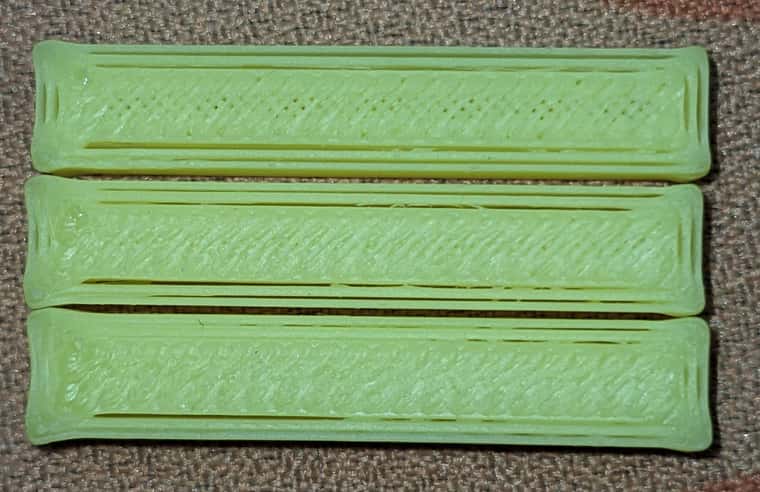
Despite underextruding a lot, the corner bulges are still there unfortunately.
The temperature sensor is a PT1000 and it is configured as a PT1000 in my config. My old sensor was also a PT1000, so I didn't have to change that in my config. The filament always behaves as I would expect it to at given temperatures, and when I start up from cold, the 3 temperature sensors in the printer all show the same temperature within 1-2 degrees (the other 2 are thermistors).
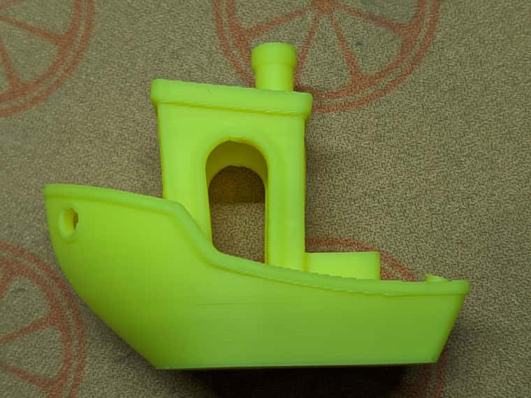
This is a benchy I printed in 20-25 minutes a few days ago on this setup.
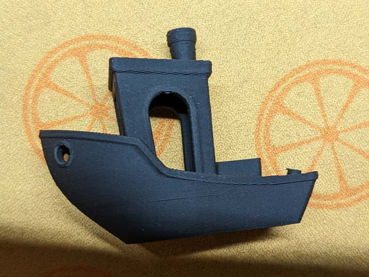
It looks pretty much flawless to me apart from the chimney having blobs on it, which was a problem I had with 3.5.0rc-1, (I've now gone back to 3.4.6) and the hull line. Which is just due to not having enough control in SuperSlicer or Orca to stop the fan from cooling as much on that layer, when the deck starts printing, without causing problems with cooling elsewhere. But there is no sign of overextrusion or high temperatures.
So I don't think there are any problems with my slicer settings or my config. Everything is now dialed in very well and the only problem I'm getting is the bulges on sharp corners. The benchy doesn't show up this issue because all corners are rounded.
-
System marked this topic as a question
-
@Threepwood said in Unable to stop severe bulging in corners with new print head:
...................... The benchy doesn't show up this issue because all corners are rounded.
But that's not the only difference, so it's a big leap to say that rounded corners are OK whereas square corners are not. For a start, it's obvious that the benchy is printed with a different filament. You've also changed from firmware 3.5 to 3.4.6. What else changed between the two prints?
Have you tried printing another benchy with the exact same settings and filament as before just to see if it's repeatable?
What happens if you print the part with the green filament with the exact same filament as the benchy and with the exact same firmware and other configured settings? I think you need to do that as a starting point to establish a datum.
-
@deckingman I have printed another benchy in this yellow/green filament and it has come out the same, but without the blobbing on the chimney. The settings for both were identical.
-
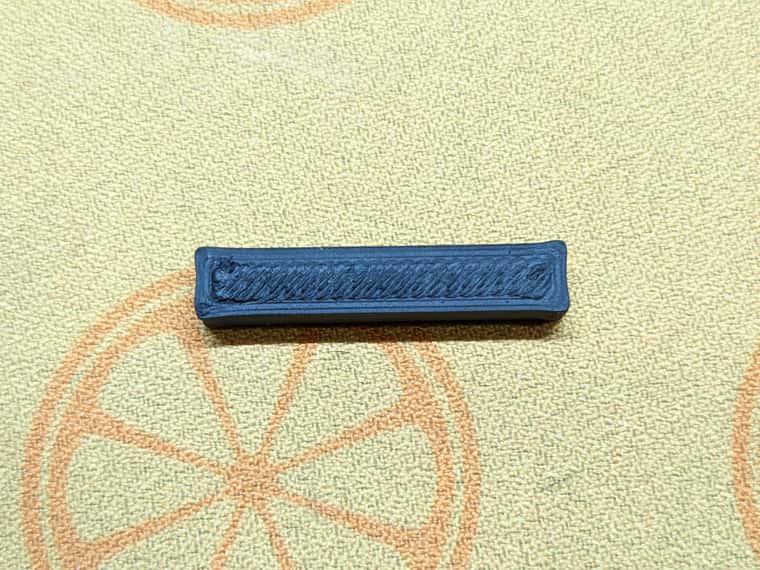
And here is the test piece in the black filament.
-
@Threepwood Well that's fairly conclusive. So what can cause bulging on sharp corners only? I can only think speed/acceleration/instantaneous speed change (jerk) or possibly pressure advance. But you say changing those parameters makes no difference. Which brings me back to a mechanical issue. But equally, you say that there is no "play" in anything and nothing is binding. Lowering the temperature doesn't help and neither does decreasing the extrusion multiplier. All of which has me stumped at the moment but I'll keep mulling it over .....
-
@Threepwood Are you using a heated chamber and what is the bed temperature? When viewed from the side, is the bulging the same on every layer or does it get better/worse with height? Clutching at straws but a benchy is taller than your test part so just wondering if bed temperature is somehow having an influence.
-
@deckingman The chamber isn't actively heated, it gets to around 50°C from the bed. For ABS I've been using 105°C on the bed for over a year. Any less and I have adhesion issues. The first time I noticed the bulging was on the bracket, which was quite a bit taller than a benchy.
I think this is some kind of issue within RRF that doesn't play well with this type of hotend. This hotend has the longest melt zone and with the lowest PA value that I've ever used, at least when the standard PA tests are used for calibration. As people with Klipper have found, changing the PA smoothing value has fixed this issue for them, but we don't have this option in RRF.
I was hoping there might be a workaround, but I'm not sure what else anyone can suggest, since we've changed everything I can think of except the hotend and the firmware.
Thank you for all your suggestions.
-
would you be willing to share your print profiles and gcode for both the benchy and the test specimen with the bulging corners?
The benchy prints completely different than just a rectangular box due to internal and external geometry differences.
My best guess at this misbehavior is high jerk and low acceleration leading to heavy deviation of the print head at corners due to inertia.
-
@Threepwood Have you tried simply increasing the PA value?
-
@Threepwood Also worth doing would be to try your test part as a single wall object with no infill to see if the corners still bulge or not? Are you printing external perimeters first and did you do the same for both the benchy and the test part?
-
@Threepwood .... also, what speed are you printing at? Does the bulging get better/worse/stay the same if you reduce print speed?
-
@Threepwood Can we just check when you printed the benchy in the yellow/green was this using the same settings (in both RRF and the slicer) as when you print the rectangular test item?
-
Hi guys,
Your questions got me thinking. I hadn't tried any other slicers. It didn't seem likely to me that a slicer setting could cause this.
This is the result of dropping the model into Orca and Cura.
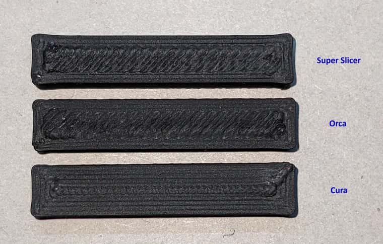
I'm finally on to something! The Orca settings are pretty much a mirror of the SuperSlicer settings with speeds and accelerations and jerk. The corners are still not perfect, but what a difference! I can probably tune out the tiny bulge in Orca or Cura by slightly increasing PA value further.
I have now also tried using Vez3D's SuperSlicer config, which changes all settings in "Print settings" "Filament settings" and "Printer settings". But I still get bulging in SuperSlicer. So it seems as if the problem isn't a setting in SuperSlicer, but in how SuperSlicer is working with my printer and firmware. I ran a search for M572 to check it wasn't changing the PA value, and it returned no M572 found.
-
@Threepwood can you post the model here you are testing? I have a goliath hotend so i can repeat the test on my machine (only difference is a use an orbiter v2).
What nozzle size are you using? -
@jay_s_uk Here is the stl. I'm using a 0.5mm CHT nozzle.
-
System has marked this topic as solved
-
Small update. I've re-run my pressure advance tests and the results at both 255°C and 270°C are around 0.08 this time. When I ran the pattern and tower tests just after installing the new hotend and got 0.02 to 0.025.
Now importantly, I have just switched from a CHT 0.5mm to a CHT 0.4mm, so I would expect an increase, but the difference is huge. I suspect that before I moved to the 0.4mm nozzle, my ideal PA vaule was actually a lot higher than the 0.02 that I had originally set it to, due to the multiple tests I ran, which showed 0.02 to be a reasonable value. I later found that the offcial VZbot firmware has PA set to 0.02.
I have no idea why the PA value has increased so much. What kind of difference should we expect to see between a 0.5mm and 0.4mm nozzle? I wonder if there was some clogging in the old nozzle, but I'm not sure that the new 0.4mm should be so high.
-
@Threepwood said in Unable to stop severe bulging in corners with new print head:
...............What kind of difference should we expect to see between a 0.5mm and 0.4mm nozzle? I wonder if there was some clogging in the old nozzle, but I'm not sure that the new 0.4mm should be so high.
The area of a 0.4mm diameter nozzle is about 0.126 mm^2. The area of a 0.5mm nozzle is about 0.196 mm^2. So although the difference in diameter is only around 20%, the difference in area is around 60%. So 60% more restriction to flow equals a hell of a lot more of a pressure build up behind the nozzle and it doesn't surprise me in the slightest that you need much more PA to compensate with the smaller nozzle.
I don't know what method you use to find the PA value but it was clearly too low. I also don't understand why "the official VZbot firmware" only states a single value when there are so many parameters which can affect pressure build up in the hot end - not least of which is nozzle diameter closely followed by the viscosity of the filament which in turn can be greatly affected by the temperature one uses.
By way of some additional data points, I'm currently running a Bondtech LGX Ace close coupled to a Slice Engineering Mosquito. This has a small melt chamber and the shortest filament path between the extruder outlet and the hot end inlet known to mankind. With a CHT 0.5 mm nozzle, the PA settings I've established after extensive testing are 0.03 for ABS and ASA at around 255 deg C, 0.04 for PLA at 185 deg C, 0.06 for PET-G and Tglass at around 230 deg C.