Please help understanding coordinated (bed, nozzle, ABl, ....)
-
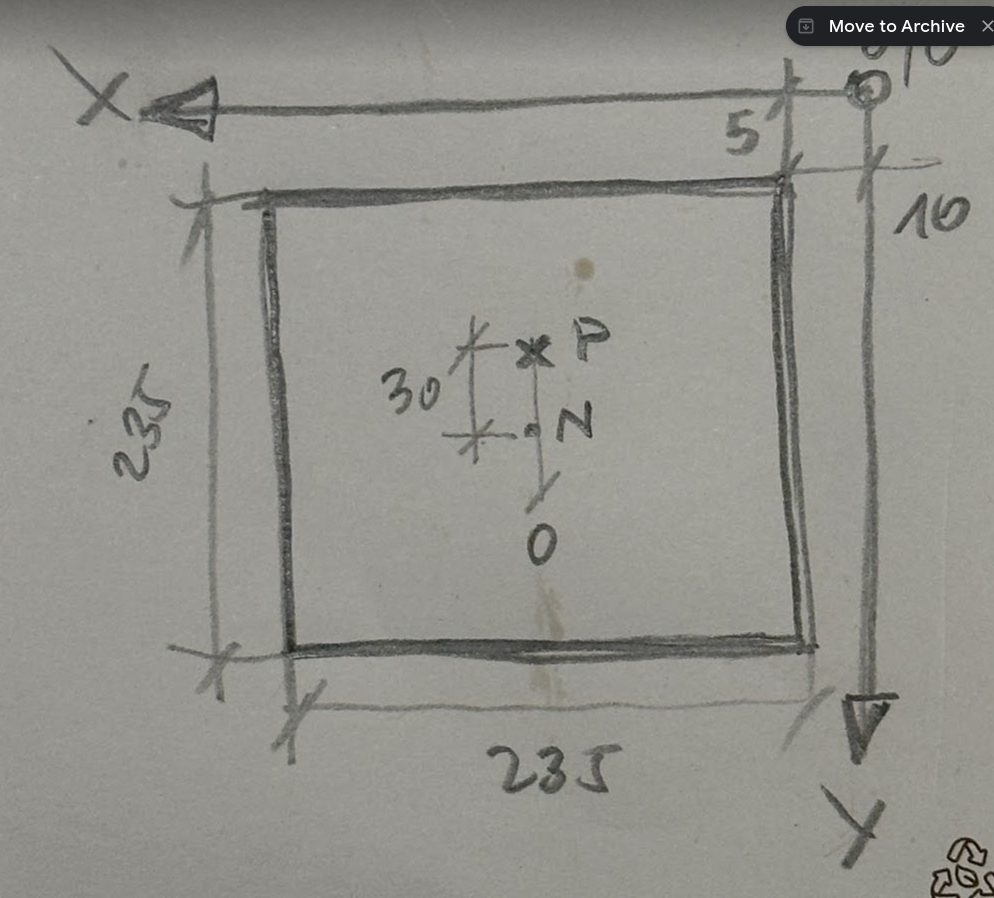
This is a picture of my setup. 0/0 is back right (Ender5 CoreXY setup on a DuetWifi). Bed is 235x235. Probe is a Klicky located 30mm from the nozzle to the back.
I just can't understand what I need to set coordinates for abl, etc ...
Probe trigger values: (it this correct? Is the Y offset measured in a way, that you take the nozzle as 0/0 and calculate from there? So -30 in Y?)
G31 P500 X0 Y-30 Z12My dual z-setup look that way:
M671 X-70:240 Y115:155 S4Is that measured from bed zero, or from 0/0? Do I need to take Y-30 offset into consideration?
Grid setup for ABL is completely off. The nozzle can reach ALL positions within the bed. The probe can reach all position with an offset of 5mm to the inside.
Can someone please help me set this up?
Thanks!!!
-
@izeman the first thing to do is either swap the X and Y axes or redefine where (0,0) is and reverse one of the axes. Currently you have a left hand coordinate system, so your prints will come out mirrored.
Duet WiFi hardware designer and firmware engineer
Please do not ask me for Duet support via PM or email, use the forum
http://www.escher3d.com, https://miscsolutions.wordpress.com -
@dc42 If I didn’t care about that: That's default for all Ender5 as I heard. So if we keep it as it is (and as it was for the carthesian Ender5 before I converted to CoreXY), what would be the next steps? Thanks!
EDIT: afaik the parts are not mirrored but rotated 180 degrees. Right?
-
@dc42 I now try to follow your advise and move 0/0 to front/left, which is pretty hard as I need to change a LOT of parameters. First one is "homing positions"
; Axis Limits
M208 X235 Y235 Z200 S0 ; set axis maxima and high homing switch positions (adjust to suit your machine)
M208 X-10 Y5 Z-0.5 S1   ; set axis minima and low homing switch positions (adjust to make X=0 and Y=0 the edges of the bed)
Would that be correct? I can't see anywhere in the manual if the first line specifies the absolute bed size, or if it relates to actual 0/0 which is offset from the corner (5mm in Y and 10mm in X in my case). Or asked the other way round: In the first line I DO SET the physical size of the bed, no matter where it lies in the coordinate system. Correct?
EDIT: Reading more on the topic I get more confused, but it seems I was WRONG. M208 uses TOTAL PHYSICAL movement for the first parameter and the second then defines where the BED's left front corner is located - in relation to the physical 0/0. This correct?
")
-
EDIT: Reading more on the topic I get more confused, but it seems I was WRONG. M208 uses TOTAL PHYSICAL movement for the first parameter and the second then defines where the BED's left front corner is located - in relation to the physical 0/0. This correct?
No.
The simplest way, to me, is to use this syntax...
M208 Xaaa:bbb Yccc:ddd Zeee:fffwhere aaa is X min and bbb is X max and so forth.
For example, on all my printers I place 0,0 at the center of the bed, so for my printer with a bed size of 300 x 200 this would be:
M208 X-150:150 Y-100:100Frederick
-
@fcwilt tbh this makes it even more confusing. And what I miss in all documention I‘ve seen is the reference system.
My head can always move to the endswitches. So in your case that would mean i have to use 0/0 as minimum. But that can’t be true.
-
@izeman said in Please help understanding coordinated (bed, nozzle, ABl, ....):
@fcwilt tbh this makes it even more confusing. And what I miss in all documention I‘ve seen is the reference system.
My head can always move to the endswitches. So in your case that would mean i have to use 0/0 as minimum. But that can’t be true.
Sorry, I thought it might help. I don't want to confuse you.
As I mentioned I like to have X=0 Y=0 at the center of the bed. The endstop sensors can be at either end of an axis. What type of sensor is used and where they are located is set my M574.
With regards to endstops, M208 merely determines what value is assigned to the logical axis position when the endstop sensor is triggered.
If the endstop sensor is at the low end of the axis the min value specified in M208 is used. Likewise, if the endstop sensor is at the high end of the axis the max value specified in M208 is used.
Frederick
-
@fcwilt said in Please help understanding coordinated (bed, nozzle, ABl, ....):
@izeman said in Please help understanding coordinated (bed, nozzle, ABl, ....):
@fcwilt tbh this makes it even more confusing. And what I miss in all documention I‘ve seen is the reference system.
All good! Not your fault that I'm confused. I just got issues when it comes to this kind of things. I'm better in other things
Ok. So my endswitches are in the back right corner. So all HIGH/MAX. So basically I can check what total movement I can have in X&Y and set this like:
M208 X0:total movement Y0:total movement
and then use G10 for axis offset to set the nozzle to the front left corner for 0/0?
-
@dc42
Aren't those just rotated axis?
If you rotate the image 180° you'll get the axis that are normally used.
Now, if I think about mirroring the image along X and then do the same along Y I'll get the same as rotating it 180°.@izeman
Did you set some tool's offset?
Bercause You have to consider those, too, for the coordinates.But basically the movement is considered from (0, 0), then it can go to negative coordinates; so, let's say (20, 20), is 20mm X and 20mm Y from where you set your (0, 0)
-
@Mr-Yod said in Please help understanding coordinated (bed, nozzle, ABl, ....):
@dc42
Aren't those just rotated axis?If you rotate the image 180° you'll get the axis that are normally used.
Now, if I think about mirroring the image along X and then do the same along Y I'll get the same as rotating it 180°.I think you are correct. If you change ONE axis from front/back or left/right then it get's mirrored. If you change both it get rotated.
-
@izeman
Did you set some tool's offset?
Bercause You have to consider those, too, for the coordinates.But basically the movement is considered from (0, 0), then it can go to negative coordinates; so, let's say (20, 20), is 20mm X and 20mm Y from where you set your (0, 0)
No tool's offset yet. I just try to get the axis/bed configured correctly first. At least that was what I was hoping for. I now have tool homed at 250/250, but can't move away from there, as moving the head to 0-249 makes it go to 250+. Direction of the axes is reversed. Even though they home correctly.
-
Ok. So my endswitches are in the back right corner. So all HIGH/MAX. So basically I can check what total movement I can have in X&Y and set this like:
M208 X0:total movement Y0:total movement
and then use G10 for axis offset to set the nozzle to the front left corner for 0/0?
No need for G10 assuming your M574 specifies that endstop sensors are at the high end of each axis.
With back/right being Xmax/Ymax then front/left will be Xmin/Ymin.
Frederick
-
@fcwilt said in Please help understanding coordinated (bed, nozzle, ABl, ....):
Ok. So my endswitches are in the back right corner. So all HIGH/MAX. So basically I can check what total movement I can have in X&Y and set this like:
M208 X0:total movement Y0:total movement
and then use G10 for axis offset to set the nozzle to the front left corner for 0/0?
No need for G10 assuming your M574 specifies that endstop sensors are at the high end of each axis.
With back/right being Xmax/Ymax then front/left will be Xmin/Ymin.
Frederick
I'm totally GAGA. There must be some knot in my brain. Sorry to act that stupidly.
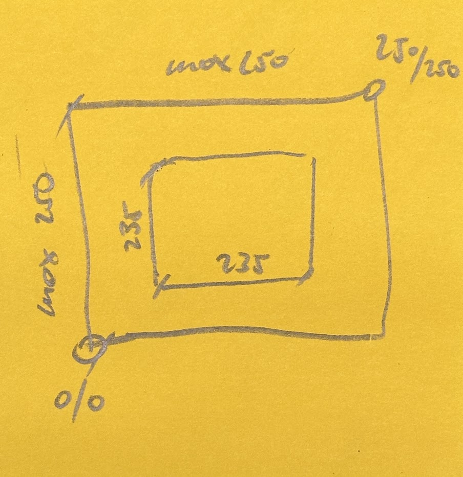
I now updated my config to move 0/0 to left/front. Bed is 235/235. The head can move 250 in both directions. What would I set my config to?
-
Well the diagram is clear enough.
Ignoring Z for now, your M208 would be
M208 X0:250 Y0:250Your M574 would be something like below, since I have no idea what pins you are using for your endstop sensors.
M574 X2 S1 P"pin_name_for_x_endstop"
M574 Y2 S1 P"pin_name_for_y_endstop"
Frederick
-
@izeman
Please note:
The homing files have to be adapted as well.
Otherwise the print head will move in the wrong direction during the homing process -
@DIY-O-Sphere said in Please help understanding coordinated (bed, nozzle, ABl, ....):
@izeman
Please note:
The homing files have to be adapted as well.
Otherwise the print head will move in the wrong direction during the homing processYeah. Just noted that
") It seems to work now. I guess ... Just running a full ABL with 20mm grid.
It seems to work now. I guess ... Just running a full ABL with 20mm grid.I just seems that my 0/0 now is like 10mm to the left and 15mm to the front of the print bed. Looks good. But when I move to the center of the bed 117/117 it moves to that number away from the real 0/0 (movement maximum) and not to the real center which should be 117+10/117+15.
-
I just seems that my 0/0 now is like 10mm to the left and 15mm to the front of the print bed. Looks good. But when I move to the center of the bed 117/117 it moves to that number away from the real 0/0 (movement maximum) and not to the real center which should be 117+10/117+15.
That is likely due to the endstop sensors not triggering at exactly 250. That is common.
Two ways to deal with it.
-
Change the M208 settings so the max values correspond to the actual physical position when the endstop sensor is triggered
-
Use G92 to adjust the logical X and/or Y position so the position at the center is correct. Put the G92 in the homing file of X and/or Y with the values needed to obtain the correct center position. One way to do this is have a G1 command at the end of the homing file with the value needed to move to the center and then have a G92 command with 0 as its value to set the logical position to 0, thus matching the physical position. For example in homeX.g you might have: G90 G1 Xnnn G92 X0
Frederick
-
-
Two ways to deal with it.
-
Change the M208 settings so the max values correspond to the actual physical position when the endstop sensor is triggered
-
Use G92 to adjust the logical X and/or Y position so the position at the center is correct. Put the G92 in the homing file of X and/or Y with the values needed to obtain the correct center position. One way to do this is have a G1 command at the end of the homing file with the value needed to move to the center and then have a G92 command with 0 as its value to set the logical position to 0, thus matching the physical position. For example in homeX.g you might have: G90 G1 Xnnn G92 X0
Two issues with that:
So instead of saying I can move 250/250 I tell the printer it can only move 250-10/250-15? It's not easy to find the "real" 0/0 when you're homing at some random 250/250 (which in reality could be 248/251 or something else) and then re-iterate from there where your real "0/0" is. Isn't it?
When I use G92 to move the working coordinates I have the issue that it can't pick up the klicky probe after homing again as it's location has change then ...
-