Can you take a look at this accelerometer measurement?
-
Hi guys,
I mounted an accelerometer on my c-bot
Board: Duet 2 WiFi (2WiFi)
Firmware: RepRapFirmware for Duet 2 WiFi/Ethernet 3.4.6 (2023-07-21)
Duet WiFi Server Version: 1.27
It seems to be working fine, I tried hand-shaking it for confirmation.
The " problem " is that it doesn't measure a real "peak" when mounted on my machine, al measurement seems coherent with each other so it seems fine
What should I do next? Where should I put the "peak" here?Here is a video
https://youtu.be/3LwV5iQyo7M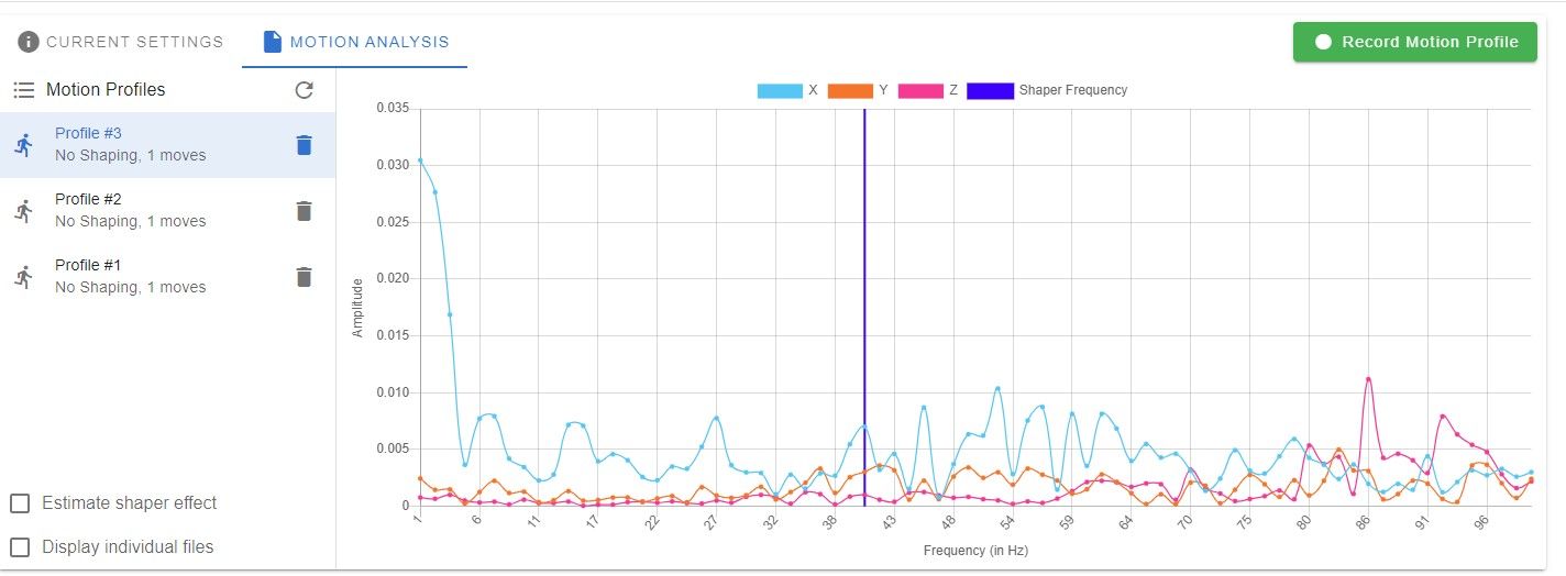
Thank you
-
@claustro you've either built a really rigid system and the speeds you are running the test at aren't conducive to vibration, or the accelerometer is not measuring the vibration close to the nozzle, or it's a highly dampened system where IS will be largely ineffective.
You could cross check your accelerometer measurements by printing a reference print (I like the https://marlinfw.org/tools/input_shaping/freq-calibr.html because it's a direct read off of a single layer print) to see if you get wildly different results.
-
@oliof Thank you for your answer.
My firmware movement speeds are
M350 X16 Y16 Z16 E16 I1                        ; configure microstepping with interpolation
M92 X100.00 Y100.00 Z1000.00 E412.00           ; set steps per mm
M566 X600.00 Y600.00 Z300.00 E1200.00          ; set maximum instantaneous speed changes (mm/min)
M203 X15000.00 Y15000.00 Z300.00 E1200.00      ; set maximum speeds (mm/min)
M201 X3000.00 Y3000.00 Z400.00 E4000.00        ; set accelerations (mm/s^2)
M906 X1200 Y1200 Z1300 E800 I30                ; set motor currents (mA) and motor idle factor in per cent
Increasing the acceleration from 1500 to 3000 I obtained this accelerometer pattern
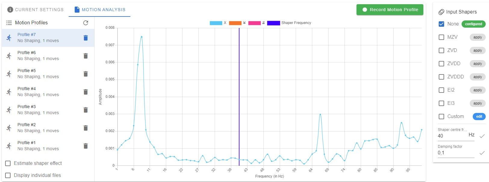
I run the test you pointed me out but I don't know if I settled up correctly.
This is the result
Now I am stuck
")
Thank you
Andreal
-
@claustro maybe @tombrazier can help us with this one (-:
<>RatRig V-Minion Fly Super5Pro RRF<> V-Core 3.1 IDEX k*****r <> RatRig V-Minion SKR 2 Marlin<>
-
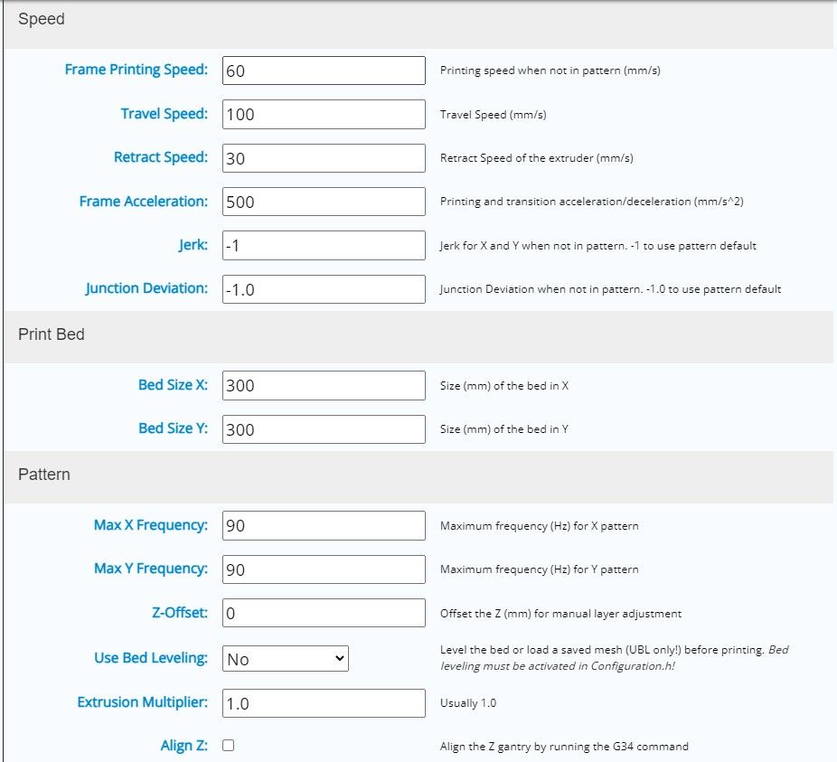
@claustro you set the acceleration to 500 in the generator. You should set it to 3000 for comparability (and make sure that the acceleration is set with RRF compatible syntax).
-
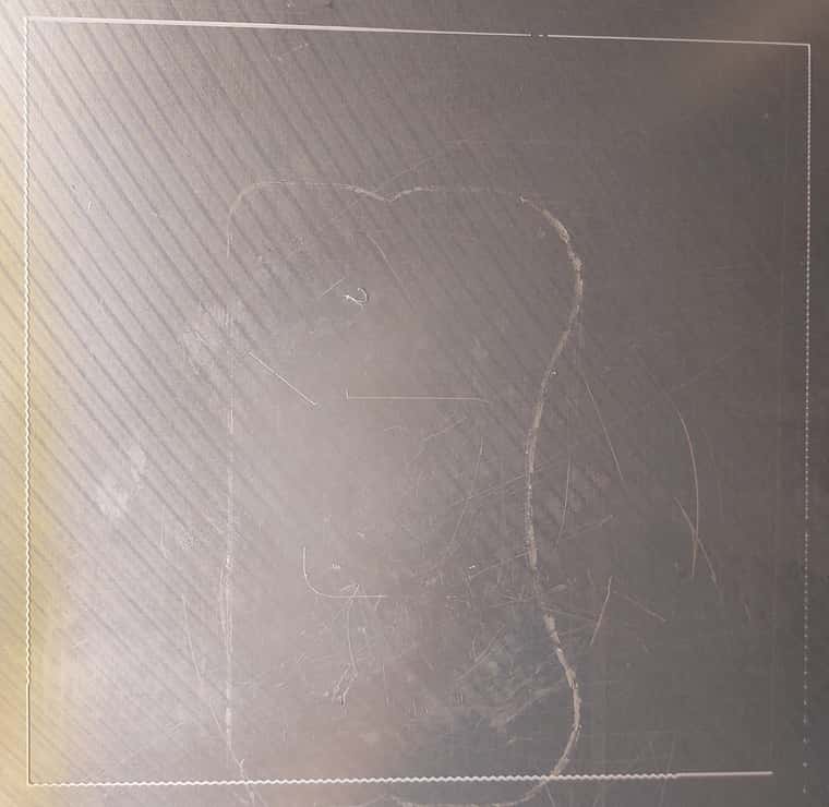
@claustro I think the image of the calibration pattern is rotated 90°. Assuming that is correct then the Y calibration is the line on the left and the X calibration is the line on the bottom.
It looks like there is pretty much no resonant frequency in the range 0Hz to 90Hz for Y and the X resonant frequency is about 4/5 of the way along the line at just over 70Hz.
Important question: was input shaping disabled when you ran the test?