Navigation

    Duet3D Logo

    Duet3D

    • Register
    • Login
    • Search
    • Categories
    • Tags
    • Documentation
    • Order
    1. Home
    2. claustro
    • Profile
    • Following
    • Followers
    • Topics
    • Posts
    • Best
    • Groups

    claustro

    @claustro

    12
    Reputation
    226
    Posts
    14
    Profile views
    0
    Followers
    0
    Following
    Joined Last Online

    claustro Follow

    Best posts made by claustro

    • D-bot reworked, very happy with results achieved

      I would like to say thank you to this forum and in particualr to @deckingman @mrehorstdmd @Phaedrux for the help in rebuilding my d-bot.
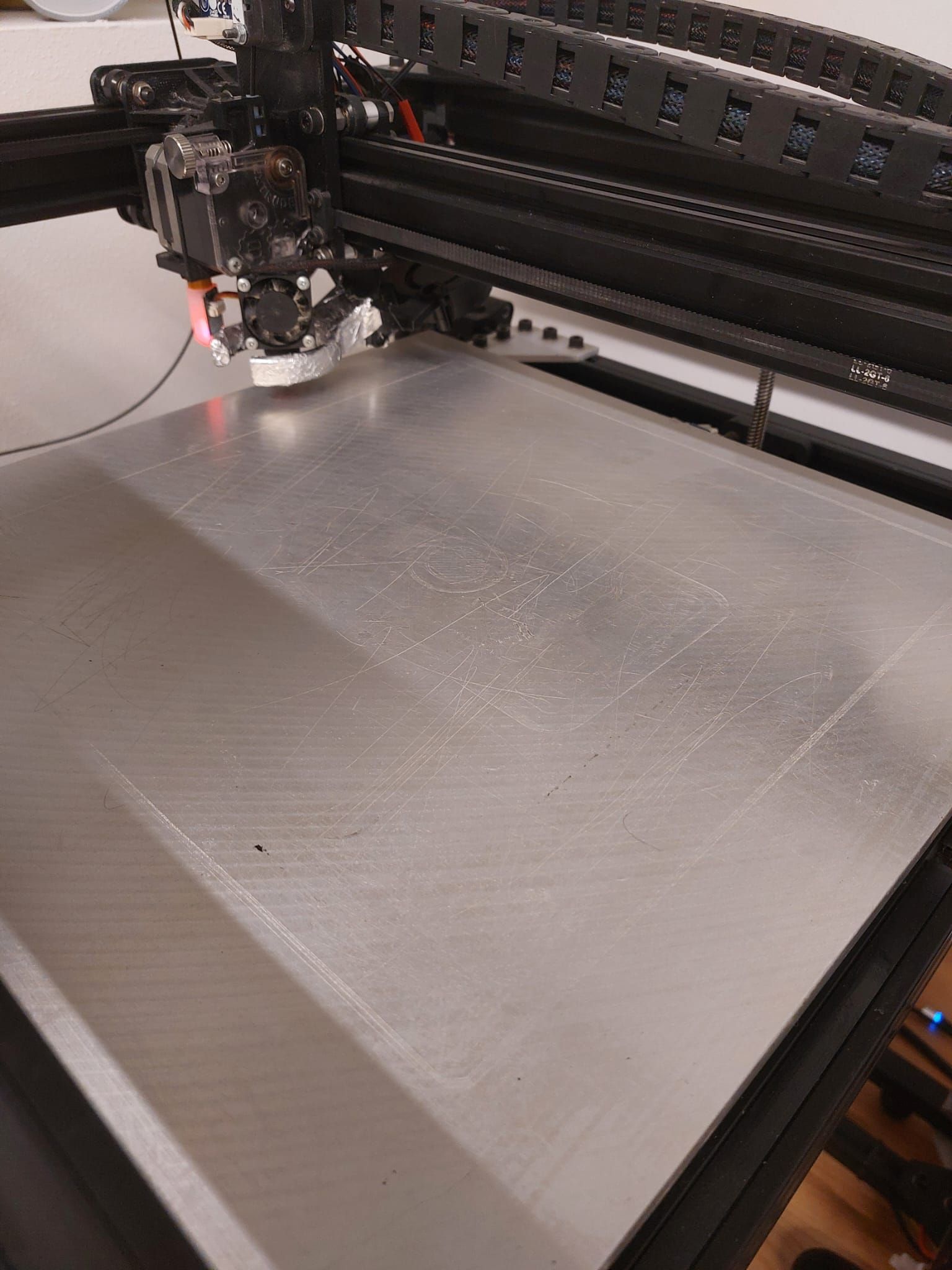
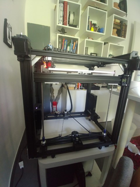
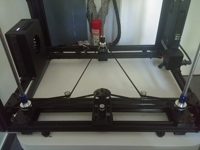
      I switched to 3 lead screw using deckingam setup. The bed is guided by only two carts on opposite angles of the printer each cart is made of 3 wheels.
      I choose to use a bed with 3 levelling screws ( in the future I would switch to levelling the bed by the lead screws) the levelling screws is mounted using mrehorstdmd setup .
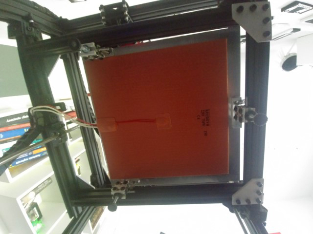
      The bed is a 330x340 die cast pei covered 8mm thick. I switched to a 220 volts heating element from Kenovo
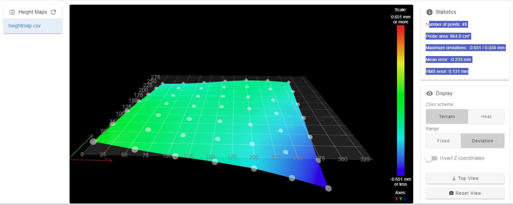
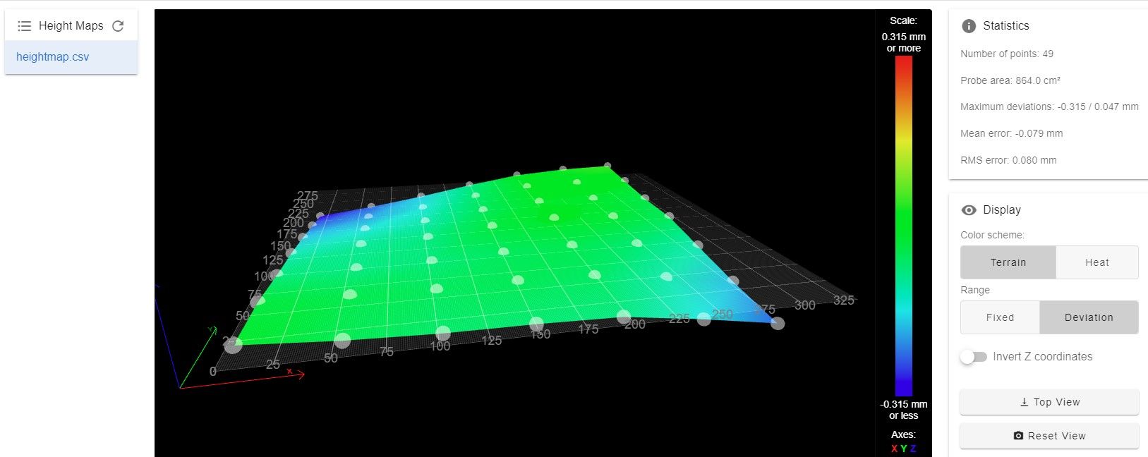
      Now I cna print on 100% of the bed surface and I swithced off the
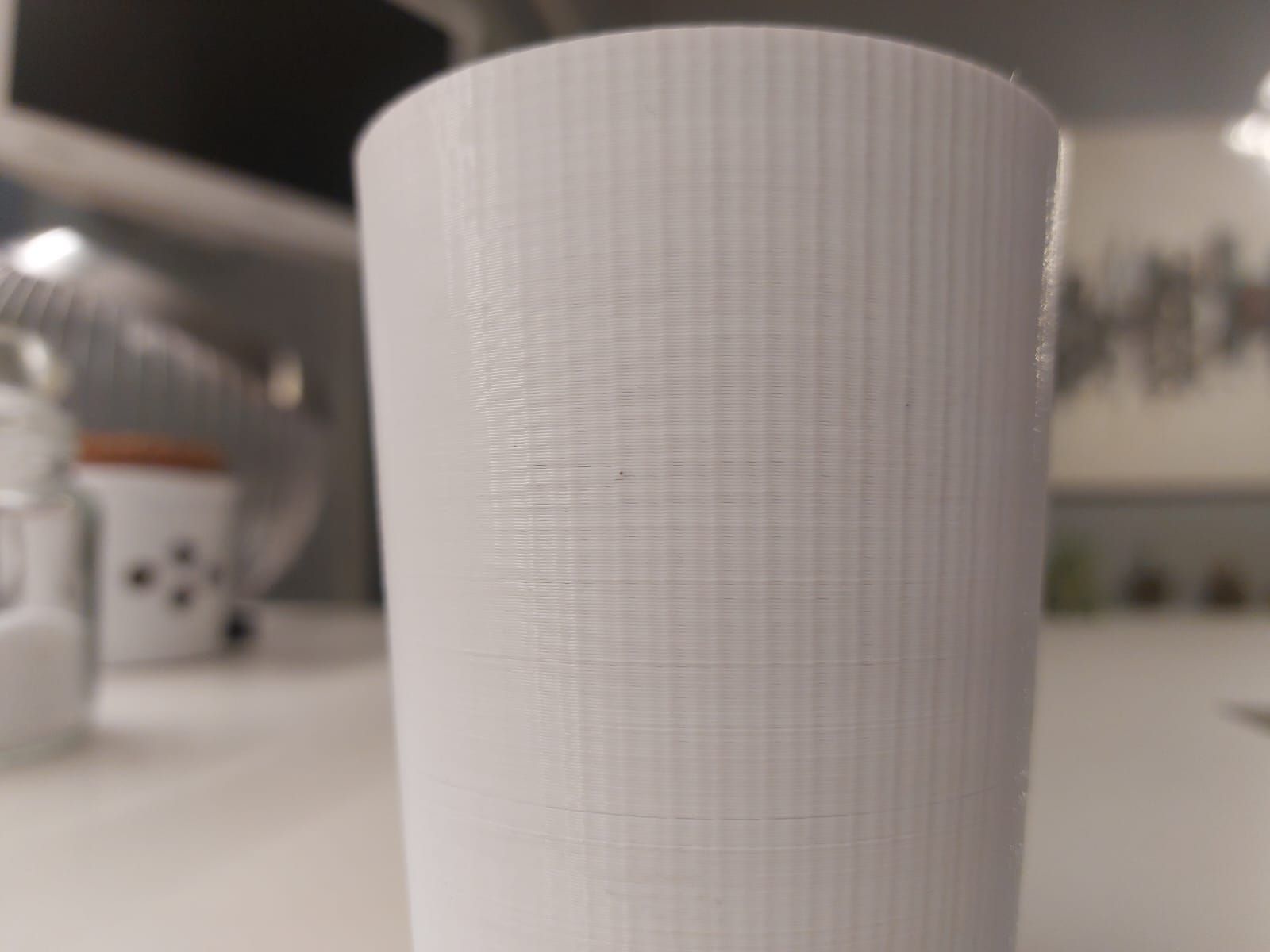
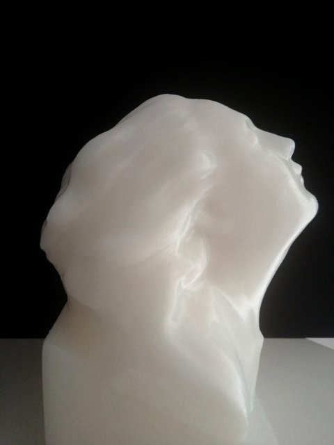
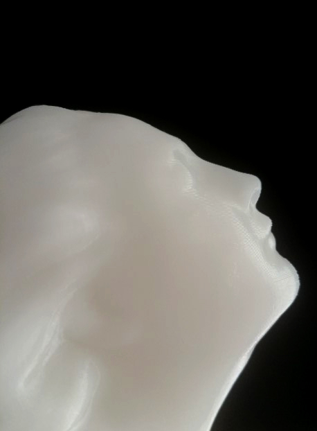
      This is my first real print and I ma very happy with it I also disabled mesh grid compensation that for now seems useless

      I still have to tweak a lot of stuff but the start seems promising!!
      0_1565538882505_20190811_094329 (Piccola).jpg
      2_1565538651298_20190811_094340 (Piccola).jpg 1_1565538651298_20190811_171116 (Piccola).jpg 0_1565538651297_20190811_171140 (Piccola).jpg
      0_1565538725202_20190811_171128 (Piccola).jpg

      posted in General Discussion
      claustro
      claustro
    • Understanding bed levelling : G29 vs G32

      I am still trying to understand the bed leveling procedure.

      Now what are the differences between G29 and G32 ?
      Which part of the configuration this 2 commands read?
      If I understand correctly the button in the web interface on "Machine Control " tab called "Auto bed compensation " run a G32 command .
      In my case this run a procedure of probing and at the end I can see the mesh grid map, so it seems to me that the G32 command run the bed.g commands, right?

      Now , with G29 command all seems to work the same except that the probel ( bltouc) doesn't deploy , so where I can add the deploy routine?

      In my other printer ,Marlin based ,I have a script that run G28 and G29 before all the printing , what script should I use for compensate bed in this case?

      Thank you for your patience

      My config.g part of bltouch
      [c];*** BLTouch
      M307 H3 A-1 C-1 D-1
      M558 P5 X0 Y0 Z1 H5 F200 T5000
      M574 E0 S0
      G31 P100 X0 Y-20 Z0.91 P1[/c]

      And my bed.g
      [c]G91
      G1 Z6 F200
      G90
      M98 Pdeployprobe.g
      G29 S2
      M557 X30:270 Y30:270 S60
      G29
      M98 Pretractprobe.g[/c]

      posted in Firmware installation
      claustro
      claustro
    • RE: Best lead screw - ball bearing mount system

      While I am trying to fix the squareness of the frame I finalized!the Z axis belt system
      This is what it came out.
      I tried to make the belt running as much as possible around the pulley with this setup all the pulley has 180 degree belt contact.
      The 2 tensioners are temporary , I am going to print a support for it
      Any suggestion will be appreciated.
      Thank you
      Andrea
      0_1559588633233_20190603_173238 (Medium).jpg

      posted in 3D Printing General Chat
      claustro
      claustro
    • RE: Best bed levelling system?

      Thank you all for such great suggestions.
      I am still not sure which way to go.

      I have a no cantilever 2 lead screw single motors setup , changing to 3?
      3 lead screws with one motor: pro lead screw always in sync con need manual adjustment
      3 lead screws with independent motor pro automatic leveling of the plane cons a little bit more expensive , need software setup , risk of out of sync motors?
      with this setup is bed leveling system still needed or the bed plate can be mounted fixed on the frame? Is it possible , and make it sense, combine mrehorstdmd bed leveling system with 3 motors lead screws setup?
      I already own the extra Z motors so costs isn't a variable in this decision.

      These are some photos of my printer take a look , any suggestion is appreciated!
      https://www.dropbox.com/sh/7bvnlctmiqushv1/AAB_oR3lea8S2ZBIfeM5EsyUa?dl=0

      Other question for D-bot owners.
      I have 3 wheels Z guide, is it worth converting y axis also to 3 wheels, I read mixed experience about it.

      @minim can you tell some more of your setup do you have some photos for taking inspiration:-).

      Thank you all
      A.

      posted in General Discussion
      claustro
      claustro
    • RE: Understanding bed levelling : G29 vs G32

      Thank you for your answer ; i read the wiki many times but many basic concept is supposed as "already know " and not explained from the basics. I am reading the reprap site also and I am starting to understand.
      Please can you answer to the last question regarding this subject,
      If I want to use a fresh bed level for every print it is sufficient put G32 in the slicing software start script

      posted in Firmware installation
      claustro
      claustro
    • Comprensive 3d printer tweaking guide?

      Hi all.
      I am not a very old and experienced 3d printer user,but during this 4 years , from the time I bought my first 3d printer, many things are changed.
      When I started ,calibrating the step per unit and feed rate was te only and more "complicated "things to tweak for improve 3d printing quality and precision.
      Now , we have a lot of stuff to play with ( pressure advance , jerk, ecc..). and I am quite overwhelmed form all this options.
      Would be great to build a "complete guide to 3d printer calibration" collecting in a single place all suggestions and procedures spreaded in this forum and all over the internet.
      Is there someone with time and knowledge able to start something like this ?
      What do you think?

      posted in Tuning and tweaking
      claustro
      claustro
    • Best way to manage vertical forces on lead screw

      Hi guys , I am planning to change my D-Bot Corexy Z axis setup. My bed is quite heavy ( 330x330x8 aluminum ) and I would like to manage better the vertical forces applied on the lower ball bearing adding a thrust bearing.
      This is what I am thinking about.

      0_1556321536406_v3 forum eng.jpg

      I have another question .
      I saw people fixing the lead screw both on lower and higher part of the frame with 2 KP08, and in the middle a T8 screw attached to the bed structure. It seems to me an overconstrained structure and I am thinking about using only 2 fixture point bed and lower frame.

      Thank you for your time.
      Andrea

      posted in General Discussion
      claustro
      claustro
    • RE: Indirect (bearing) laser filament monitor concept

      Thank you for sharing with us.
      I have a magnetic sensor from about 1 year and it works flawlessly.
      I don't know if laser costs less of magnetic, but the need of a bearing system in the laser sensor affect the simplicity of this device reducing or annulling the advantages over the magnetic one.
      IMHO
      .
      good idea anyway

      posted in Filament Monitor
      claustro
      claustro
    • All black D-bot

      Hi guys, I am stressing many forum members with all kind of questions on how I could improve my D-bot so I decided to post some photos for let the curious guys see the " responsible " of all my questions 🙂

      The printer: ( for now)

      • Duet wifi ( thx @deckingman for the case)
      • changed from cantilevered to 4 point sustained bed
      • 3 wheels Z carriage
      • 2 lead screw with belt driven by single motor
      • Dual 24 v Meanwell PSU
      • Switched after some weeks to direct with titan extruder
      • Magnetic Duet filament sensor that works great ( I can't understand why duet crew didn't make it available on the market)
      • Cable chains on Z and hotend
      • Originale Bl touch
      • Self designed radial fan for print material that work very well

      Upcoming change.

      • I bought a 330x340x8 PEI covered here https://clever3d.de/ with 3 regulation point ( thank you @mrehorstdmd )
      • New heated bed 220V 750W 300x300 so I'll remove a PSU
      • I would like to rework my Z axis that works good but not as good as I would like my actual idea is to shift to 3 lead screw driven by single motor ( thank you @Phaedrux for all the input). I need to decide how many guides to use if stay with the actual 4 or go for 2.

      In the future I am tempted to test 3 Z motors for autolevelling but for now I want to follow advise of all the people that suggest me that a good solid printer don't need bed leveling more than occasionally

      For me aesthetic is very important so cable wire is a large part of the time spent building this printer,

      3_1556406994994_e.jpg 2_1556406994993_d.jpg 1_1556406994993_c.jpg 0_1556406994993_b.jpg

      posted in My Duet controlled machine
      claustro
      claustro
    • RE: Printed parts deformed

      @engikeneer thank you very much for your input . I think I discovered the problem in a far from perfect printed angle.
      I gonna try to check every angle I let you know 🙂

      posted in Tuning and tweaking
      claustro
      claustro

    Latest posts made by claustro

    • RE: Printed parts deformed

      @Veti In this case it would difficult for me to add more information than what I provided because I didn't know my config file could be involved. The last time I edited it, excluding z offset was many weeks ago, but I didn't notice the defect before, maybe because lastly I printed many "organic" parts 🙂 Also, the broken belt drift my attention to a hardware problem, I never thought about a configuration problem till all other causes was canceled 😞
      Anyway, my printer is now more squared 🙂

      posted in Tuning and tweaking
      claustro
      claustro
    • RE: Printed parts deformed

      @Veti My post wasn't a critique for someone. It was just a follow up of my story 😉

      posted in Tuning and tweaking
      claustro
      claustro
    • RE: Printed parts deformed

      @engikeneer

      Thank you all for your help. I managed to solve the problem ...but not as expected:-)
      I reprinted main frame parts. disassembled all the printer and reassembled as perfectly as I can. Changed the belts
      Then I printed the test part and it come out exactly as the previous one!!
      At first, I thought about an error in the stl so I designed another one by my self but also this one come out skewed.
      Then a flash in mi mind! how a can a part come exactly skewed ass the previous one even after building and rebuilding the printer? I checked the configuration file and the m92 was
      M92 X101 Y100 Z1000 !!!!
      Maybe changing stuff in config I mistyped a 1 and so the problem suddenly appeared!
      M92 X100 Y100 Z1000 and now print a 300x300 square with diagonals in 0.5mm tolerance.

      posted in Tuning and tweaking
      claustro
      claustro
    • RE: Printed parts deformed

      @engikeneer thank you very much for your input . I think I discovered the problem in a far from perfect printed angle.
      I gonna try to check every angle I let you know 🙂

      posted in Tuning and tweaking
      claustro
      claustro
    • RE: Printed parts deformed

      @Veti Yes I know what a parallelogram is I understand what my problem is but I misread your post as " your frame does not have TO HAVE 90 degree angles" so this was
      confusing me 🙂

      posted in Tuning and tweaking
      claustro
      claustro
    • RE: Printed parts deformed

      I am missing something.
      Phaedrux told me to square EG and EF so if I understand correctly he is holding me that the angle between EG and EF must be 90 isn't it?
      I measured the distance between EF and NG and it is constant at every point.
      So I am assuming it EF and EG are parallels.
      This is true for all the part of my frame
      so AB, BP,PQ,QA.
      So I thought that the problem is that my frame is skewed as I sketch in my post above.

      I really cant' understand why the frame don't have to be at 90 degree 😞

      Can you tell me a practical process for "square " EG and EF other than measuring distances if the angle isn't the problem?

      posted in Tuning and tweaking
      claustro
      claustro
    • RE: Printed parts deformed

      Thank you for your help.
      My situation is this .

      This is face 5 ( x/y top plane). I can't understand best way to fix this.Immagine.jpg

      posted in Tuning and tweaking
      claustro
      claustro
    • RE: Printed parts deformed

      The printed part come from another printer and seems ok.

      I am rechecking all the structure but I am missing something .
      I'll try to explain my situation.

      Assuming the d-bot is a dice it have 6 faces each one delimitated by 4 vslot peaces

      1 left ( AEQR)
      2 back (AGBL)
      3 right (BFPS)
      4 front (NPOQ)
      5 bottom (RLSO)
      6 top (GFNE)

      I measured the distance between the vertical parts of the frame
      A-Q
      A-B
      B-P
      P-Q
      All are the same so they should be parallel

      I measured the diagonal on the top ( face 5) here I have a small differences of about 1.5mm between the 2

      But when I measure with a 90-degree square the angle EG and GF thera arent at 90 degrees with a maximum difference of about 0.75 degrees that produce a difference of about 2mm at the and of the square.

      I don't know if this is somehow clear 🙂
      From where I can start solving this?
      Senza titolo-1.jpg

      posted in Tuning and tweaking
      claustro
      claustro
    • RE: HE Temperature goes beyond selected after pid tuning

      thank you very much for your help, I am gonna re-crimp the cables

      posted in Tuning and tweaking
      claustro
      claustro