[feature] Adaptive / Feedforward Temperature setpoint
-
@timschneider said in [feature] Adaptive / Feedforward Temperature setpoint:
So I use 2.85 mm filament
I thought it was just me using up everyone else's 2.85mm filament! If I ever get my Trident-ish machine finished, I've got a Titan extruder with volcano CHT nozzles (probably 1mm nozzle dia) tool earmarked for it, to get through all the old stock (after it's spent time in the filament dryer), and print big things fast! So some form of temperature feedforward would be good.
Ian
-
@timschneider As this feature has been added (https://github.com/Duet3D/RepRapFirmware/commit/b300085b44b2fe403d231a674b3b29f702c6b66f), have you got any suggestions for the tuning method that I could add to the feedforward documentation?
M309 in the Gcode dictionary has been updated to say:
Parameters
...
Tddd:eee:fff... Feedforward temperature increase coefficients. The number of coefficients provided must equal the number of heaters configured for the tool when it was created (see M563). Supported in RRF 3.6.0-beta.2 and later.
Aggg Feedforward advance time in milliseconds, maximum 100. RRF will attempt to apply the temperature and PWM adjustment this time in advance of the start of the corresponding move. This advance time may not always be achieved, for example when commencing movement from standstill. Supported in RRF 3.6.0-beta.2 and later.Notes
...
The units of T are degrees Celsius per mm/sec of filament forward movement.No notes on the A parameter.
Ian
Bed-slinger - Mini5+ WiFi/1LC | RRP Fisher v1 - D2 WiFi | Polargraph - D2 WiFi | TronXY X5S - 6HC/Roto | CNC router - 6HC | Tractus3D T1250 - D2 Eth
-
@droftarts
Hi @droftarts
I use the following tuning method:- determine the lowest possible temperatur
Temp_basefor the filament, e.g. extrude with F30 (0.5 mm/secSpeed_base) so that the filament is melting and will bond to each other - define your desired extrusion rate, e.g. 35 mm³/sec -> calculate the required extrusion speed -> around 5.5 mm/sec (
Speed_desired) for 2.85mm filament -> F330 - Extrude the filament with the desired speed + 20% and increase the temperature of the hotend till you are able to extrude at the desired speed. Note the needed temperature for that speed
Temp_required. The extrusion length should be at least two times your hotend length. The 20% increase is some kind of error margin for non linear extrusion and when the fan is on. - calculate the needed temperature boost with
Temp_boost = (Temp_required - Temp_base) / (Speed_desired - Speed_base)
For Example PLA
Temp_base = 190
Temp_required = 230
Speed_base = 0.5 mm/s
Speed_desired = 5.5 mm/s
Temp_boost = 40 / 5 => 8 => T8
Edit:
Temp_basewill be the temperature you set in your slicer for that material. - determine the lowest possible temperatur
-
@droftarts
I have updated the description so that it hopefully becomes clearer how much material has to be extruded and why you should aim for a 20% plus error margin and that you should use the temp_base for slicing. -
@dc42
thank you for implementing the temperature feedforward.
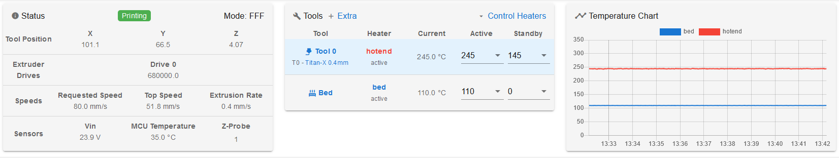
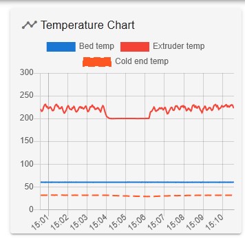
It took me a while to get it installed on a machine and test it, unfortunately I was not able to get it working. Maybe its a pure display thing, but I do not see the temperature increase I was expecting.I set
M309 P0 S0.06 T8 A100and was extruding at 245°C with 0.6mm/sec, so I was expecting an temperature increase of 4.8°C but the temperature in DWC was still at 245°C.the following chart is showing the print process and a pretty stable temperature without the increase and decrease of the temperature feed forward.
The printer is on

-
@dc42
The problem is the A100 - without the A param it works.
What is the purpose of the A param - I thought it is kind of a look a head and will set the temp increase in advance.
But it will not work for short moves.To reproduce:
G28 X Y M568 P0 R160 S230 T0 G91 echo "will not work" M309 P0 S0.05 T8 A100 G1 X1 E1 F120 G1 X1 E1 F120 G1 X1 E1 F120 G1 X1 E1 F120 G1 X1 E1 F120 G1 X1 E1 F120 G1 X1 E1 F120 G1 X1 E1 F120 G1 X1 E1 F120 G1 X1 E1 F120 G1 X1 E1 F120 G1 X1 E1 F120 G1 X1 E1 F120 G4 S5 echo "will work" M309 P0 S0.05 T8 A0 G1 X1 E1 F120 G1 X1 E1 F120 G1 X1 E1 F120 G1 X1 E1 F120 G1 X1 E1 F120 G1 X1 E1 F120 G1 X1 E1 F120 G1 X1 E1 F120 G1 X1 E1 F120 G1 X1 E1 F120 G1 X1 E1 F120 G1 X1 E1 F120 G1 X1 E1 F120 -
@timschneider we knew that large A values will not work correctly, because there need to be enough moves in the queue that have been committed in order to look that far ahead. I think A40 should generally work: can you try that?
Duet WiFi hardware designer and firmware engineer
Please do not ask me for Duet support via PM or email, use the forum
http://www.escher3d.com, https://miscsolutions.wordpress.com -
@dc42
I dared to try
Using firmware version 3.6.0-beta.4 and with following command in my config.g:
M309 P0 S0.06 T10 A40
I can confirm that temperature modulation based on flow rate works.I used the small model below as a preliminary experiment, printed at a nominal temperature of 190 deg C. (usually I print this material at 212 deg C).
Remarks:
During the first layer the temperature jumped to over 220 deg C but with the bed at 45 deg C this was unnecessarily high to achieve bed adhesion. To avoid such surprises I managed to disable this feature for the first layer alone using
the macro command
M309 P0 S{(layer_num == 0 ? 0 : 0.06)} T{(layer_num == 0 ? 0 : 10)} A{(layer_num == 0 ? 0 : 40)}
which yields M309 P0 S0 T0 A0 for ths 1st layer only; then the temperature set for the 1st layer in the slicer is used unchanged.I needed several retries because I was getting a heater fault error right at the 1st layer. The increase was too sudden I guess. Only after I reconfigured the heater fault detection I could continue the print:
M570 H1 P15 T20 ; wait 15 sec, allow 20C deviationThe maximum temperature increase happened at the widest height of the model and was about 5 degrees, but only a short time.
Most of the time the print temperature stayed around 192C, that is, only 2 degrees higher than set. Although the speeds were set up to 300 mm/sec, due to a layer time limitation and weak cooling fan, the print went quite slow with 20-35 mm/sec.The deviation between target and actual temperatures can't be assessed during the print, because the increase introduced by this feature is done in the firmware - this is as expected, but raises the need of a plug-in in DWC to preview the effect.
Manually overriding the extrusion speed live during the print (or perhaps using M220) did cause a corresponding increase in temperature, as it should be.
It is unclear to me whether extrusion rate increases caused by non-linear extrusion configuration (M592) also cause temperature increases. In theory, his could lead to a vicious circle, because a temperature increase by itself also promotes a higher extrusion.
I learned that this feature works only increasing the temperature, never decreasing it. That means that one is compelled to choose a nominal printing temperature (the one set in the slicer) that should be low enough that no decrease is necessary due to a smallish flow. This could happen to be inconvenient, depending on the average flow and temperature range needed. This method is suitable to adapt temperature in regions with higher flows, overcoming potential bottlenecks.
A better approach would have been (in my opinion) to consider the nominal temperature to correspond to the average flow rate, allowing both increases and decreases. In most cases no special tests or calibrations would be needed with this method; for example, setting 205C for PLA, thus allowing a range of +/- 15C=30C. Flow rate "spikes" would be still accounted for. This way, small details and overhangs would benefit too (a more common concern than printing at very high speeds, if quality is important).
In other words, as it is implemented, you would set for a benchy a nominal temperature corresponding to the chimney top - suboptimal I think.
Print details:
Duet 2 WiFi + 0.4 nozzle, PLA, 0.12 mm layer height, 0.3 mm layer width, one wall only (to challenge the operation!)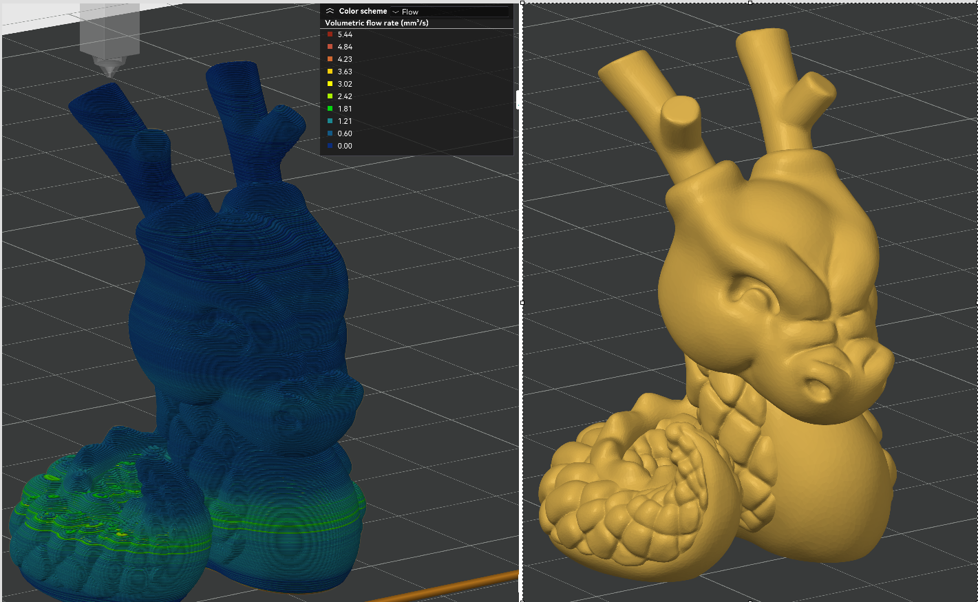
And I got this result:
The print was quite good in my opition, and was not worst than a good one done without the feature under same conditions. Still learning.I have gathered some experience using the post-processing script mentioned above. It is difficult to believe how felicitous that script manages the temperature/flow relationship. That solution works differently though: It controls speeds in such a way that the flow matches the temperature when the temperature can't be changed fast enough; it also smoothes the flow rate - sounds dangerous, but works surprisingly well. Unfortunately, it is only a post-processing script with the respective disadvantages. The author was told that such feature belongs to the firmware realm - here we have it.
I think this feature of the version 3.6.0 will be vastly underestimated. I consider it a big jump, really.
By the way, the description in the documentation of M309 should be corrected. It states:
"This feature is intended for high flow hot ends or pellet extruders. It's not normally needed on regular hot ends with a 0.4mm or similar size nozzle where the temperature drop caused by extrusion is less than 1C."
The feature may be inteded as described, but it is not limited to mere anticipation of temperature fluctuation of the nozzle due to changing flow. In fact, it contributes to a much better control of a key parameter, namely temperature. I myself will be using it quite often, I think.Hope I helped a bit.
-
ok,
A40is working - but shouldn'tA100act likeA0ifA100can not be maintained? Instead it was acting likeT0.@Triet
thanks for you tests! You can maybe increase the layer height to increase the volumetric flow rate, as the T parameter from M309 is multiplied by the speed in mm/s of the filament (extruder) - not the movement speed of the X and Y axis. Your absolute maximum flow rate is about 5.44 mm³/s which is about 2.26 mm/sec for 1.75mm or 0.85 mm/sec for 2.85mm filament, which corresponds to 227.6°C or 213.5°C. Thats a steep increase, unless you have a powerfull heater, your printer will not be able to follow. I use T8 with an 60W heater and 2.85mm filament. I run my prints with 25 - 40 mm ³/s. -
@timschneider said in [feature] Adaptive / Feedforward Temperature setpoint:
0
This was a test I spontaneously decided to do without planning, but it turned out unsuitable for the purpose of temperature modulation. The maximum flow rate of 5.44 mm3/s (using a 1.75 mm filament) happened very shortly and was not representative at all. I did notice the jump though - causing a heater fault at my first try.
I also use a 60 W heater, in a copper block (E3D style) and an original CHT nozzle. It can achieve a 25C increase faster that one would think, but certainly not fast enough if the model consist of parts with disparate flow rates in succession. And that is exactly the test case I am printing right now:
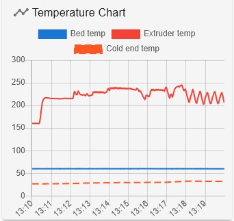
As you can recognize here:
The temperature is set at 195C but settles at around 199C +/-2C, it can't follow as you say. The range would be much wider if it could. But there are some layers with predominantly high flow, I am waiting to see how the temperature behaves then (I am staring at the display).
Based on my experience using the postprocessing script mentioned above, the maximum temperature lag was about 5C, in most cases only 3C - but that script uses a different method, where the flow rate is adapted (smoothed) to match the predicted temperature, very clever in my opinion. The temperature/flow rate relationship is defined there by entering three points of desired temperature at the given flow rates, quite easy. I could envision that a similar method is implemented in the firmware. But even this T-Parameter is a thing as it is now. I have learned to appreciate the value of temperature control and am quite excited about it.
More tests following.
-
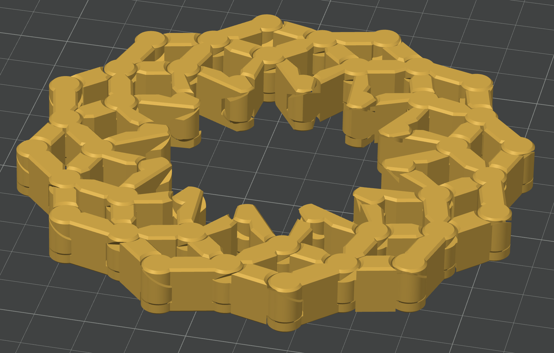
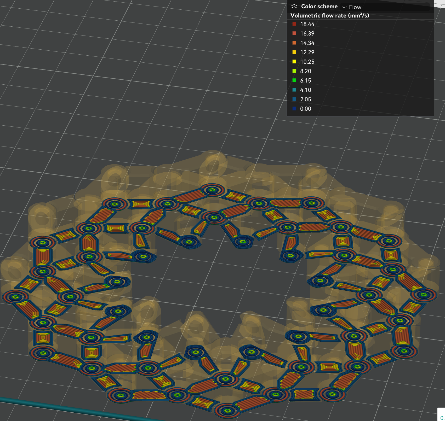
@timschneider That model (I would call it "the "mother of hinges"), went well - all hinges were moving free without play (after forcingly "unfreezing" them the first time). I can infer then than the temperature variation does not pose a danger in maintaining correct dimensions, in this case at least.
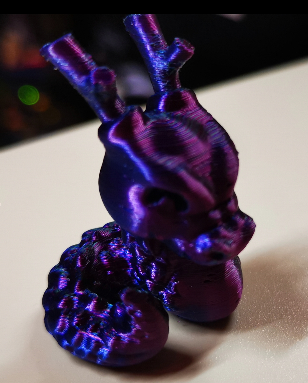
Now I am choosing a more representative test model with an ample variation of flow rate, which at the same time allows us to assess artifacts, without being excessive large or long to print.
This JUN - the Jungle Queen (visual benchy) has a plethora of details and is not too small.
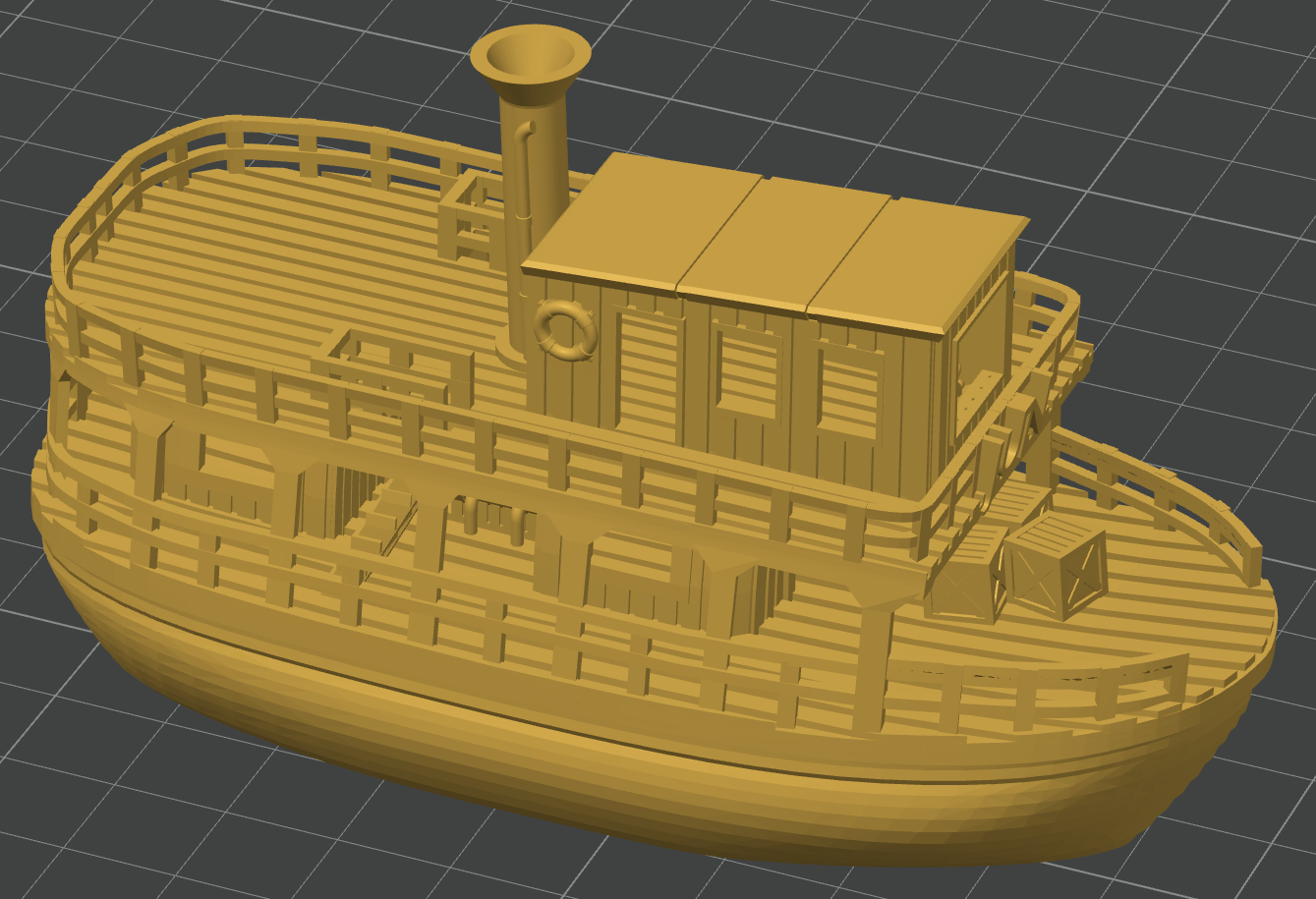
Results:
Printing with at 195 C, 0.2 mm layerheight, (0.4 mm nozzle), solid infill with 0.6 mm layer width, and sparse infill speed set at 300 mm/sec (but not reached) and still using M309 P0 S0.06 T10 A40, Orca Slicer was showing a flow rate up to 29 mm3/s, but that is not true. The real maximum is about 20 mm3/s, enough of a range. Extrusion rate smoothing was set to 90 mm3/s to avoid abrupt transitions.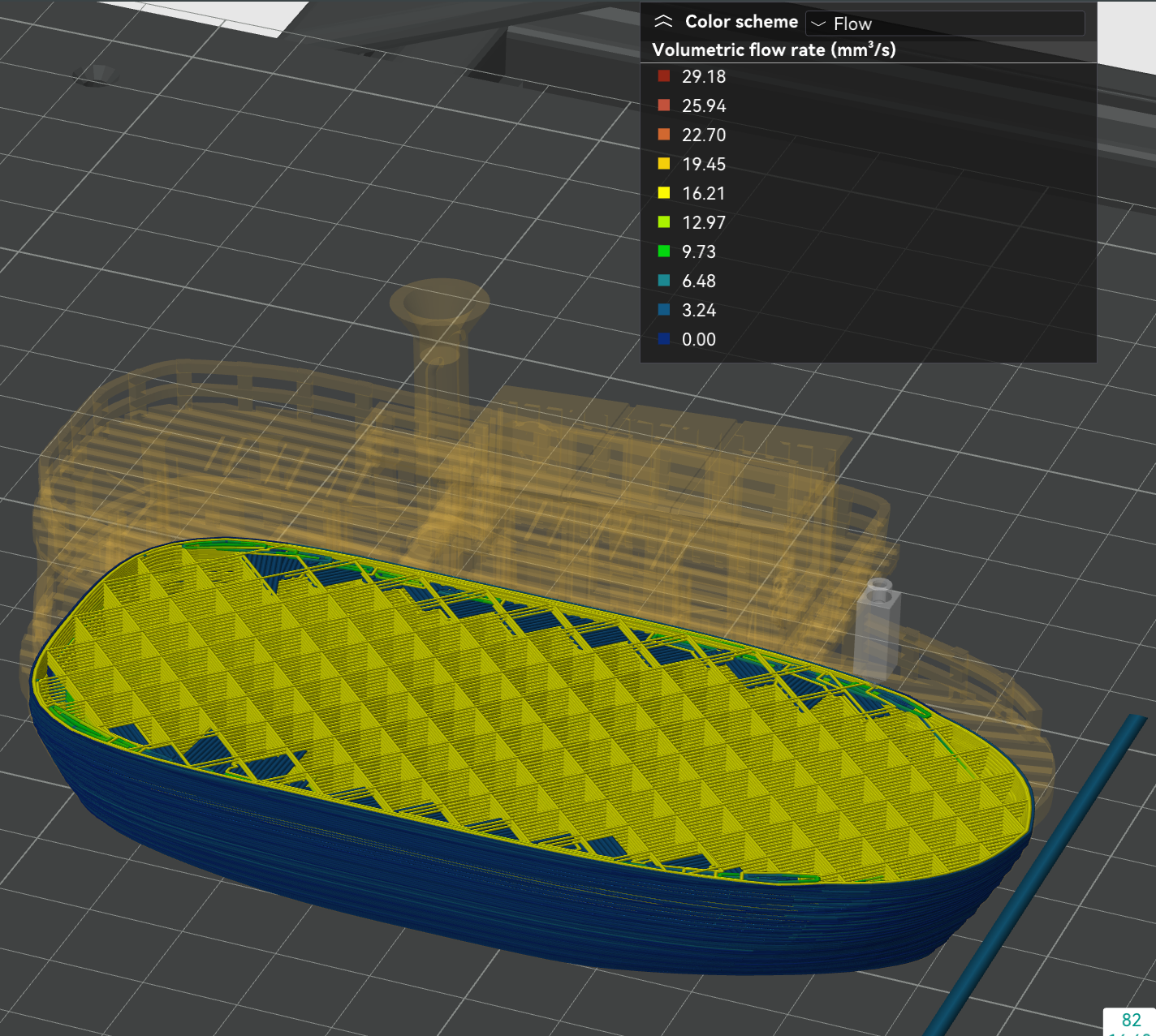
The temperature occassionally reached >240 C in the high flow areas. In very slow areas, it was decreased (!) down to 190 C. Most of the time, is was about 200C.
The print shows very crisp details, reminding me of previous cases using the postprocessing script. This is obviously the result of printing the small details with a suiting lower temperature.
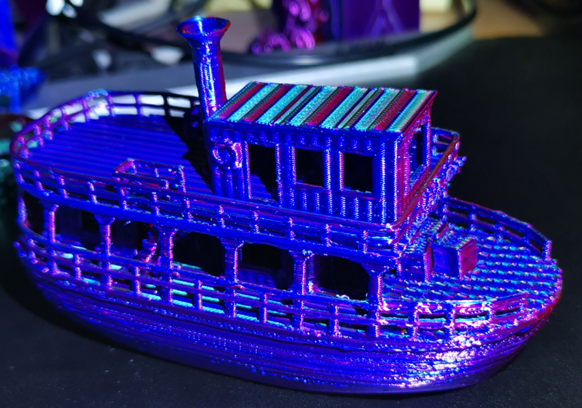
Despite some suboptimal slicer settings (happens when printing in a hurry), the print went well and it looks better than in the picture.
Remarks:
I noticed that right at the begin of the print the temperature is higher than it should be (although I disabled this temperature modulation feature for the first layer), but immediately begins to fall as the print of the 1st layer progresses. My suspicion is that the firmware looks at the flow of the movements in the print queue in advance, but ignoring the command disabling the feature. But the command it is there:
and when it is processed, the temperature fails again to the nominal 195C. It looks like a slip to me.Furthermore, I still got heater faults (even after releasing the check conditions), but strangely, this happened at a moment where the temperature was quite stable after having significantly changed before. So it looks to me like the firmware notes a temperature deviation, but does not update that deviation timely as the temperature has changed and stabilized. Perhaps that part of the firmware should be revised.
This time, a decrease in temperature compared to the nominally set print temperature (195 C in this case) took place at some point. So I withdraw the objection I made before, although I don't quite understand how this is controlled in detail. I assume that the T parameter defines a slope determined by changes of temperature in relation to changes in flow, but where we are in that characteristic curve, I don't know.
Summarizing, I am very pleased with this enhancement. I still stand on my prediction that this feature will stay extremely underrated. I recommend to try it out.
-
 undefined Triet referenced this topic
-
@timschneider In case you are interested, this video offers insight to flow modulated temperature control:
Variable Temperature 3D Printing – The FUTURE of 3D Printing?
-
I am finding this feature really interesting. For pla and a 0.4 nozzle, I find
M309 p0 S0.06 T6 A40
works ok. I use a base temperature of 200, and first layer temperature of 215. First layer prints at 220-225, as I use 20mmsec for perimeter and 40mm/sec for infill. Using a revo 40watt heater and revo cht nozzle, temperatures change quite quickly (low thermal mass). Experimenting with higher speeds, inner perimeters and infill print fine at 140mm/sec (DWC reports about 22cumm/sec) - accurate weighing of resulting print showed that there was no under extrusion. I am not currently using non-linear extrusion. I have a single nozzle delta, so sometimes change filament mid print to get a multicolour effect. The adaptive feed forward is good for this as the base temperature is high enough to load and prime the new filament, but there is little oozing so you get a clean change. This is what a manual filament change looks like
The print quality with adaptive feed forward seems excellent, and still finding the limits of how fast one can go.
-
@Adrian52 I found that the active (=target) temperature is not updated, either in DWC or in the Paneldue. It is impossible to know how far the current temperature deviation is.
Besides, I had to increase the S Parameter to about 0.3 to get a quicker change of temperature. Nontheless, I get heater faults from time to time, although I have loosened the check using the command M570 H1 P100 T45, which is incredibly forgiving, as it allows a deviation of 45 C deg to persist for up to 100 sec...
-
@Triet I guess if one is using the feedforward in the way intended, the temperature shown is the target temperature. I have been playing with the parameters, trying to understand how they work. I am trying out a 0.25mm nozzle, which has an extrusion rate of about 8.8cumm/sec with 0.125mm layers at 140mm/sec, which is think corresponds to about 3.6mm/sec for 1.75 filament. A T parameter of 12 seems to give the expected increase of just greater than 40deg over the base temperature. I think there is a bit of under extrusion at this speed with the 0.25 nozzle, but checking that out. For my standard 0.4 cht nozzle, 0.2 layers give about 22cumm/sec at 140 mm/sec, that is about 9mm/sec filament. Using T5, this gives the expected increase of about 45deg above base temperature. I dont think the cht nozzle is underextruding under these conditions. I have just started using an S parameter of 1.0, and this seems to work fine with the 0.25 nozzle - not tried with the 0.4 nozzle yet. Tried increasing the A parameter to 50, and the feed forward stops working.
I have been using M570 H1 P15 T45, and not been getting heater faults. The revo nozzle setup I am using has a low thermal mass, and seems to be controlled very well by the duet. -
@timschneider said in [feature] Adaptive / Feedforward Temperature setpoint:
ok, A40 is working - but shouldn't A100 act like A0 if A100 can not be maintained? Instead it was acting like T0.
I've reduced the maximum allowed from A100 to A50 in rc2, which I think should work.
[EDIT: Adrian's post above suggests that it doesn't.]
Duet WiFi hardware designer and firmware engineer
Please do not ask me for Duet support via PM or email, use the forum
http://www.escher3d.com, https://miscsolutions.wordpress.com -
@Adrian52 said in [feature] Adaptive / Feedforward Temperature setpoint:
I guess if one is using the feedforward in the way intended, the temperature shown is the target temperature
That's correct, the target (as displayed by DWC and PanelDue) remains the same but the feedforward correction is added to it internally.
@Triet said in [feature] Adaptive / Feedforward Temperature setpoint:
It is impossible to know how far the current temperature deviation is.
I'll look at adding the current feedforward boost to the object model.
EDIT: I've added the boost parameters to the OM.
-
@dc42 On my system, the highest A value that works is 48
-
To see if I could get the hotend to follow the forward temperature more closely, I tried removing the silicone sock from the revo heater, to see if I could get faster cooling. I redid the pid tune without the sock, and this is the plot printing a 100mmx20mm cube that has three small cylinders attached to one end. The cube walls print at 140mm/sec, and the cylinders around 20mm/sec. The cube has no fill or top, but the initial part shows printing the bottom infill
It then cycles between the fast cube walls and the slow cylinder walls. I was suprised how well controlled the temperature is under these conditions. The print weighed exactly the amount predicted by the slicer, so no underextrusion. The cube walls were printing at 22cumm/sec (o.4 nozzle, 0.2layers). The S parameter was set to 1
Would be interesting to plot the feed forward boosted temperature on the temperature chart - is this possible?
-
@Adrian52 you could plot it with BtnCmd if its in the object model
