Sovol SV08 Multiple Motion System Upgrade.
-
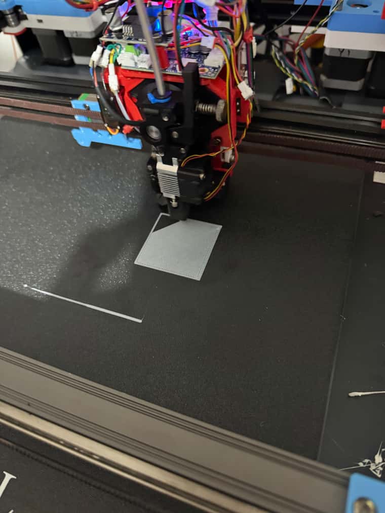
Gradually getting there with bed levelling.
Found my two probes trigger at slightly different heights, plus the nozzles are also at different heights too - so will add some manual adjustment capability in before trying first print.I can't get auto 4 axis calibration to work - it keeps saying it is not supported for the kinematics. I've tried coreXY too and it still says the same thing.
So I have settled for now on probing and a level of auto adjustment in bed.g that seems to work.
My HomeZ does still seem to mess up the gantry levelling, and I am getting some issues with probes getting stuck on in the software.
But I think with this bed.g I now have a pretty flat Z axis after a few iterations.
M671 X410:-60:-60:410 Y420:-10:420,-10
M400

while true
    G1 X300 Y200 F20000
    G30 P0 X300 Y200 Z-99999 ; probe near a leadscrew

    var adjust1 = (sensors.probes[0].lastStopHeight)


    G1 X20 Y20 F20000

    G30 P1 X20 Y20 Z-99999 ; probe near a leadscrew

    var adjust2 = (sensors.probes[0].lastStopHeight)


    G1 X20 Y200 F20000
    G30 P2 X20 Y200 Z-99999 ; probe near a leadscrew

    var adjust0 = (sensors.probes[0].lastStopHeight)


    G1 X300 Y20 F20000
    G30 P3 X300 Y20 Z-99999 S-1 ; probe near a leadscrew and calibrate 4 motors


    var adjust5 = (sensors.probes[0].lastStopHeight)

    echo var.adjust1, var.adjust2, var.adjust0, var.adjust5

    if (abs(var.adjust1) < 0.01 && abs(var.adjust2) < 0.01 && abs(var.adjust0) < 0.01 && abs(var.adjust5) < 0.01)   || iterations > 6
        break


    G91

    if abs(var.adjust1) < 1
        set var.adjust1 = var.adjust1 * 2
    if abs(var.adjust2) < 1
        set var.adjust2 = var.adjust2 * 2
    if abs(var.adjust1) < 1
        set var.adjust0 = var.adjust0 * 2
    if abs(var.adjust1) < 1
        set var.adjust5 = var.adjust5 * 2


    M584 A1 P6
    G1 A{var.adjust1}
    M584 A2 P6
    G1 A{var.adjust2}
    M584 A0 P6
    G1 A{var.adjust0}
    M584 A5 P6
    G1 A{var.adjust5}


M400
G1 Z0 F2000
G92 Z2.55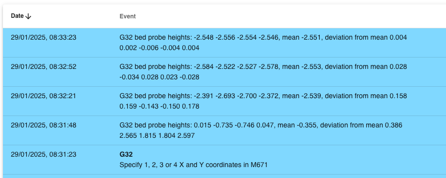
-
Current thinking on first Z Hopper prototype
an MG90S servo - for Z offset, first layer meshing and Z hopping only for other layers.
The mechanism will unfortunately add another around 10mm to the depth of the extruder due to the tiny MGN7 linear rail.
I don't think the 1LC board 5V can handle the stall current of about 700ma - so will add a buck convertor onto the 24v input supply. Will put the servo on IO-0.out on the 1LC.
-
@dwuk Hi David,
I did a quick sketch to show you the cam concept. I can't upload a photo, so I put the link below. You should erase the spaces.
I tried to use arrows to explain which part is which.
You should add a mechanical switch to limit the lower Z position of the extruder. When the extruder reaches the lower Z limit, the spring should have slight tension—this will likely provide sufficient accuracy.
Additionally, if you add a screw to adjust the lower Z limit, you can fine-tune the adjustment to ensure both extruders are on the same plane.
https :// freeimage . host / i/2Qk9jcl
-
@_MRT_ Thanks very clever- like it.
Especially the fact that is should allow more precision and also the servo motor will not need to take the full weight in its rotational axis. Will add limit switch in too as you suggest.
Have added a screenshot of your photo below.
-
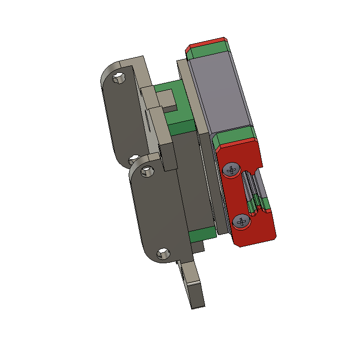
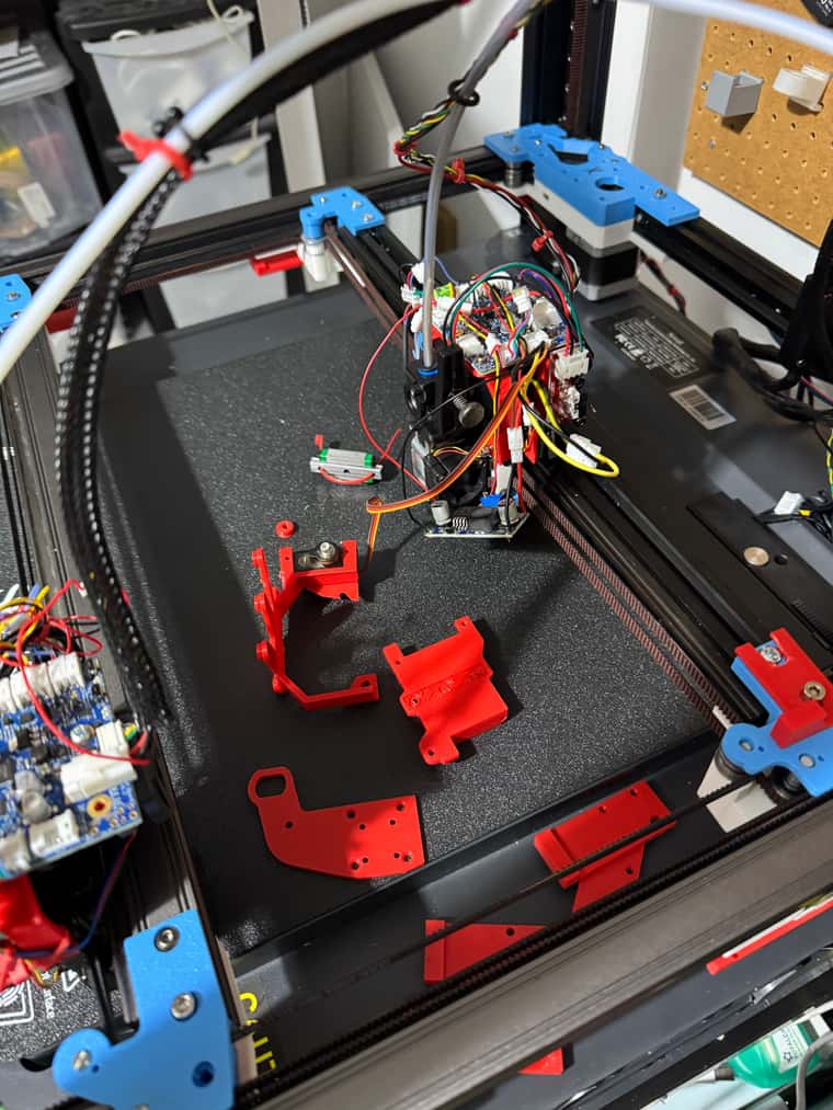
@dwuk Basic rigid Cam version created for first test.
Will then experiment with adding springs as suggested by @_MRT_
Need however to limit the width as much as possible to avoid clashes with the other head on the same gantry. I guess I could move the servo and cam onto the other side and reposition the X end stop.
The Cam is offset 0.75mm from the centre of the shaft - so I am guessing this means about 1.4mm of movement within the range of about 140 degrees of the servo.
Will add in screw height adjustment and end stop later.
-
@dwuk Servo wired up and tested. On the 1LC board io_0.out, with an LM2596 DC to DC convertor to bring down the 24V input to 5V for the servo.
Prototype parts printed - just need to install them and test them - might be a few days due to other commitments.
-
Back from holiday - lots of deliveries while I was away - so ready for IDEX.
Made mistake with Order I think and bought 30 Buck Convertors instead of the 3 more I need - but only about £12 for all of them. All got a nice variety of end stops - both optical and mechanical.
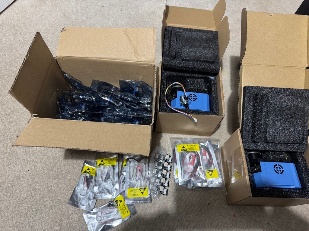
Also now have various different stepper motors to try for z hopping in addition to servo. Think a stepper motor might be easier to control as will be able to set it as an AXIS which will move in line with head moves when doing bed mesh adjustments. I think the tiny geared stepper motor in the middle from ThePiHut with a cam is probably the best solution. But the larger linear stepper also a possibility.
First test of servo lifter - need to make some changes - probably to move belts to be on fixed part rather than moving part. Also should probably move servo back a bit plus add a bearing to the cam,.
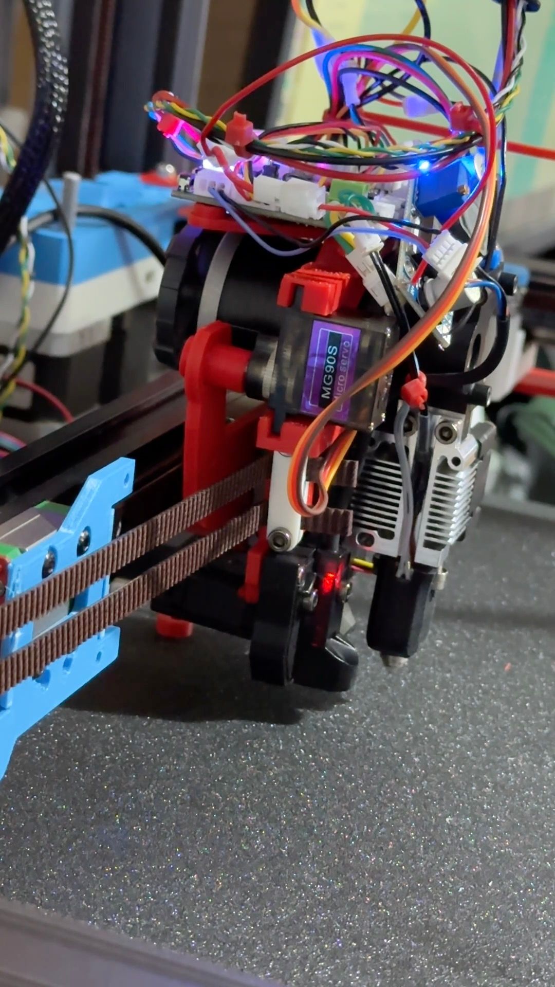
But anyway it works - see short video.
https://youtube.com/shorts/AQexkpbFp64?si=ysh9GKfc63iHuNRg -
@dwuk said in Sovol SV08 Multiple Motion System Upgrade.:
add a bearing to the cam
That's what I meant before when I said use excenter bearings. Three of them in a planetary gear fashion could also replace the mgn-linear guide and have a wider footprint.
I'm not good with CAD or napkin drawings, otherwise I'd sketch up an example. Probably best suited for a pancake stepper. -
@o_lampe Thanks - I thought It was probably getting closer to what you were suggesting - but I am afraid I still don't really understand the planetary gear suggestion, especially how it would eliminate any side to side movement - but it sounds interesting if it can eliminate the need for the linear rail and if possible remove some depth from the solution.
I am thinking I am going to need some sort of gearing to have enough power to lift the print head.
-
Not getting consistent Z heights with the new 'z-hopper' extruder, so remodelled it with a bigger linear rail (MGN9 vs MGN7), plus also made the rail bolt directly onto the back of the main X carriage - this will hopefully eliminate a lot of the wobbles.
Also corrected the issue with the belts being on the moving side, rather than the fixed side.
Also improved G32 / bed.g macro a bit - but would really like to get G30 S4 working properly - rather than having to the do calculations myself.
-
@dwuk One point of concern is the tiny screw that connects the excenter with the servo. It has to hold the whole weight of the tool?
There is also a big distance between tool-COG and the anchor point of the excenter, which adds the tendency to tilt the extruder rather than lift it. (risk of racking?)I just thought: worm gear! The smallest motor will be able to lift the tool and it comes with inbuild self locking.
-
@o_lampe Good point - may have to strengthen that part up - I just wanted to make it slightly adjustable/easy to print a small extra bit.
I can't get the servo any closer if I mount it on the side - but may be able to move it behind somewhere - especially if I attach it to the rail part rather than the extruder.
The new design will be easier to take apart and put back together to try out different options.
One of the motor options I bought - the linear stepper is worm/lead screw based so will try that out at some point.
-
Managed to get proper G32 4x Z motor levelling to work
G32
Leadscrew adjustments made: -0.435 -0.410 -0.334 -0.474, points used 4, (mean, deviation) before (-0.421, 0.027) after (0.000, 0.000)Not sure why the adjustments are so large - but the Z height seems to be quite consistent across the bed now on Gantry A.
I found the problem by looking at the code in GitHub and trying to work out the reasons for the 'Kinematics not supported' message coming out - in the end I found this line section - and thought numLeadscrews might not be set - and the condition of xSize not matching ySize was the problem - as I had specified a comma instead of a colon in my M670 for the lead screw positions.
M671 X410:-60:-60:410 Y420:-10:420,-10I see now that M98 P"config.g" would have found this problem - so need to run that more often.
if (seenX && seenY && xSize == ySize) { for (float& v : lastCorrections) { v = 0.0; } numLeadscrews = xSize; reprap.MoveUpdated(); return false; // successful configuration } -
@dwuk said in Sovol SV08 Multiple Motion System Upgrade.:
servo lifter
Just as a potentially useful datapoint. the very first iterations of e3d toolchanger used a metal gear hobby servo (not that one, I think more powerful one), as the tool lock motor. They quickly swapped to a small servo motor because of longevity. If this is doing Z hops then it will probably have several orders of magnitude more activations per print than a tool change in a toolchanger so I would look carefully as the service life of those servos.
-
@T3P3Tony Thanks - I am mainly just initially using the hobby servo to get the 2nd print head level with the first one - so I can do my first print, plus for some initial tests with z hopping and mesh levelling.
I've got a couple of small geared stepper motors that I think are going to work better in terms of the gcode at least - as I should be able to assign them to axis and get the movement to better synchronise with the X & Y movements. But the point about longevity might apply to those too.
I've also got some bigger ones - a Nema8 and Nema14 pancake to try too - but will need a lead screw with them probably as they are not geared.
Will have a look into what Servo Motors they used for the e3d tool changer too - so thanks.
-
@dwuk said in Sovol SV08 Multiple Motion System Upgrade.:
Not sure why the adjustments are so large
It's just the difference between the configurated tool offset and trigger point of the probe.
Since they are all pretty close (-0.4ish), your bed level looks fine. -
Servo based z hopper working quite well now with the revised linear rail setup - so far only used for Z height adjustment on the 2nd Gantry - and managed to get them both to print ok.
To get 2nd gantry to print I created a tool T1 - that is offset 100,100 away from the main gantry -
; Tools
;Tool T1 - 2nd Gantry as X and Y
M563 P1 D1 H2 X3 Y4 F1
G10 P1 X0 Y0 U-100 V-100 S0 R0And it worked ok - had to slow speeds down on U and V axis - as 2nd gantry motors not as good as first gantry at the moment.
Now trying to get both tools printing at the same time - and can't quite figure out how to make it work - keep getting the gantries crashing in to each other - so will probably leave it until the morning.
; T2. - duplicate mode
M563 P2 D0:1 H1:2 X0:3 Y1:4 F0:1
G10 P1 X80 Y100 U-80 V-100 S0 R0
<<< Update - found problem - I was specifying P1 on G10 instead of P2 - so G10 now reads:
G10 P2 X0 Y0 U-80 V-100 S0 R0From first gantry
From 2nd Gantry
-
First successful Duet Dual Gantry IDEX test. - ( Phase 1 part 3)
https://youtu.be/A485TMKhmV4?si=gRNhVj0sPUrHJKw3
First layers not perfect and running a bit slow for some reason - but overall a big step forward.
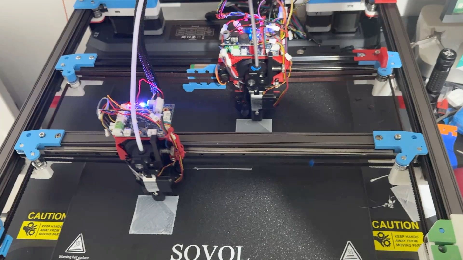
Next step - multiple motion system...
-
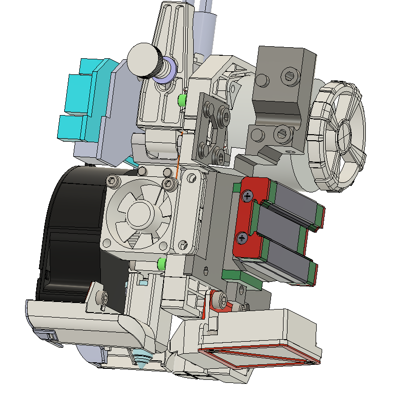
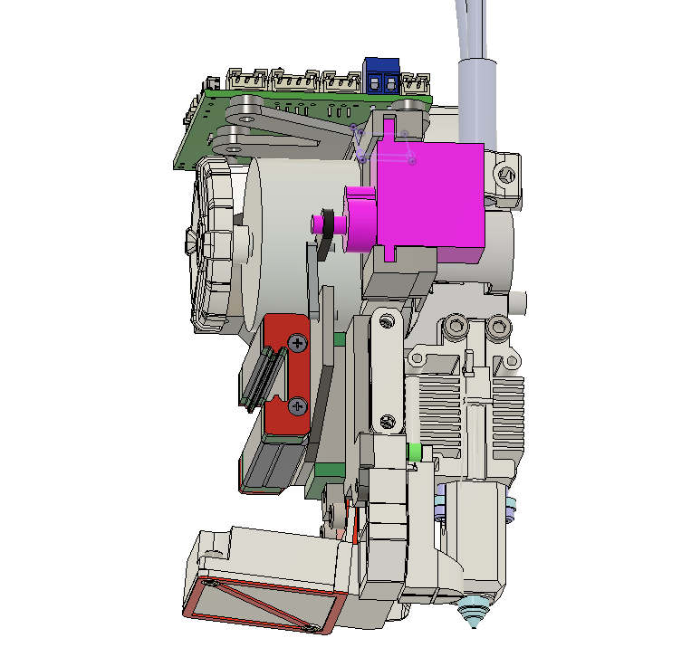
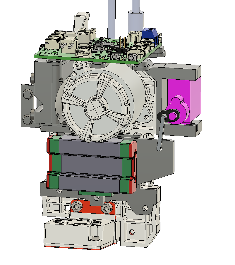
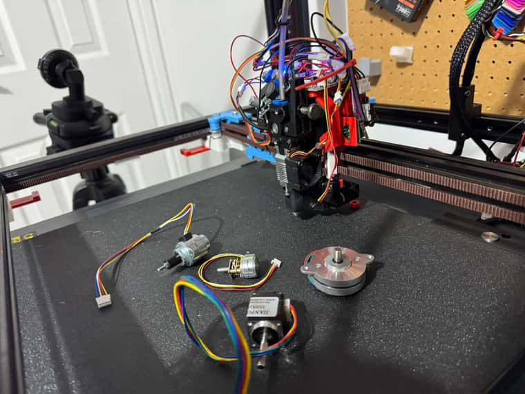
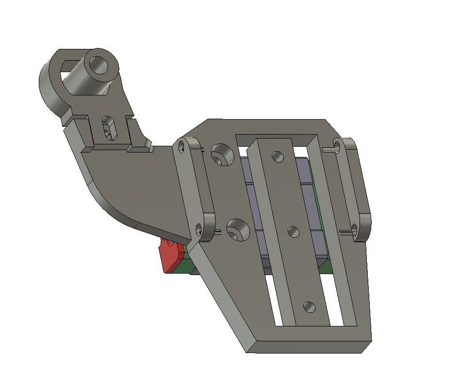
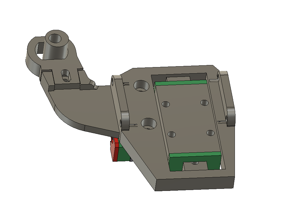
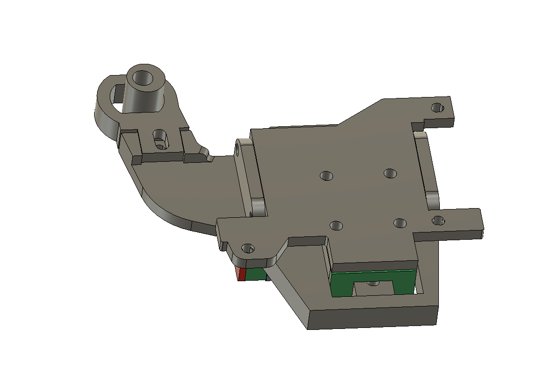
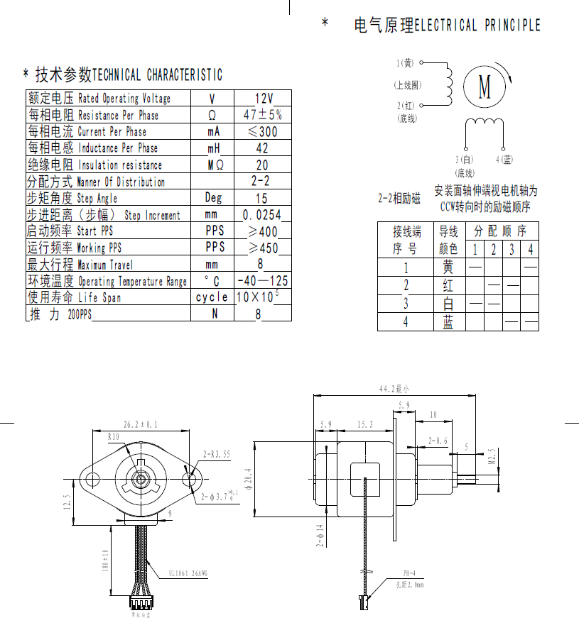
Next Z hopper option that I am going to try - this time using a linear stepper motor with 8N strength which should hopefully be enough.
Will have to run the 4 wires to it from the Mini5+ board as the tool board can only support one stepper (unless there is a clever way to wire in another driver).
Will combine it with an optical end stop - so will if I don't fix the stepper at the bottom be able to use the
vertical linear rail as a 'Voron Touch' probe too.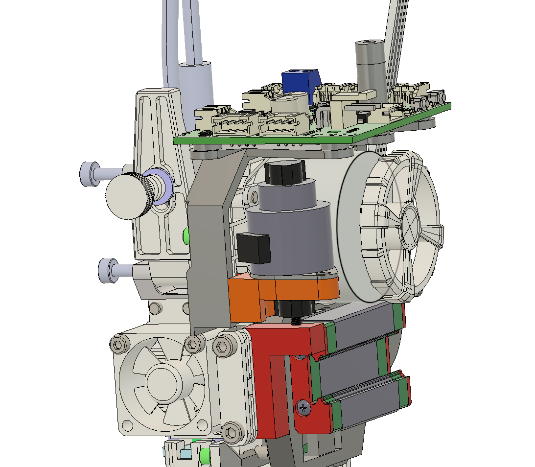
Shown in this picture with the servo option too for comparison - the linear motor is close to the centre and the linear rail too - although bending doesn't seem to be an issue despite the servo be a fair way off of the rail.
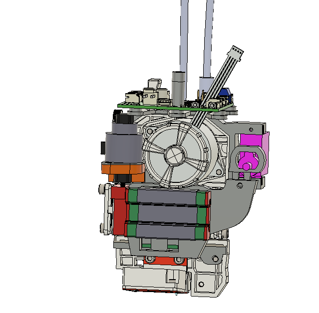
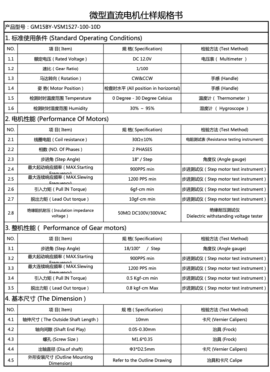
The servo motor looks quite good quality - and specs are as follows. - cost about £17 each including shipping.
Will only need to use about 2mm of the 8mm range.
-
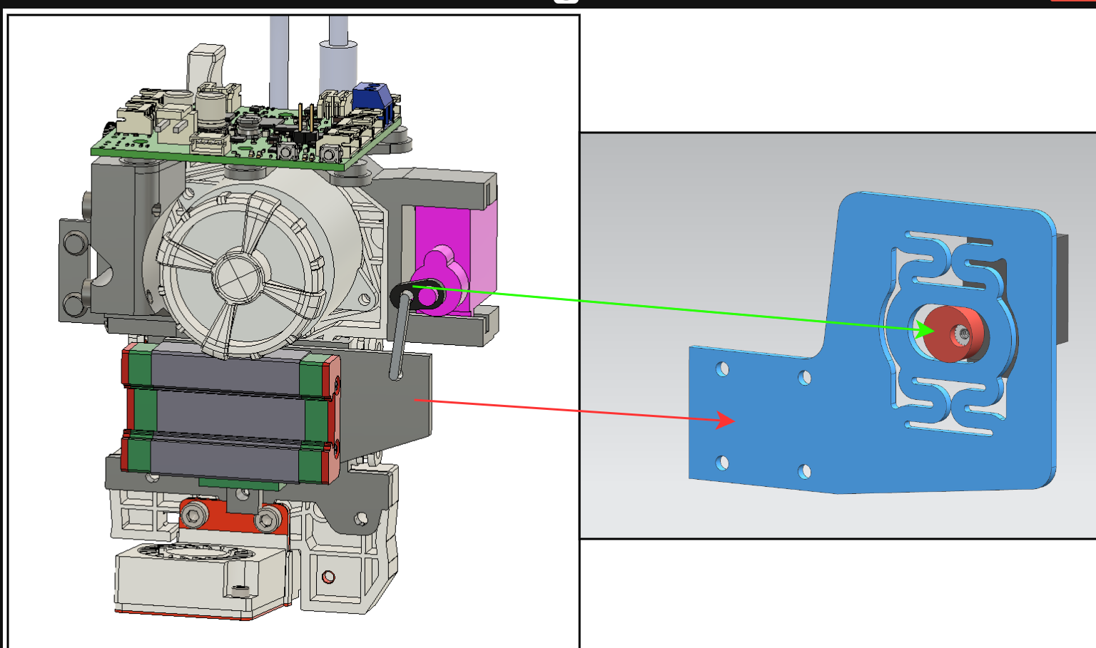
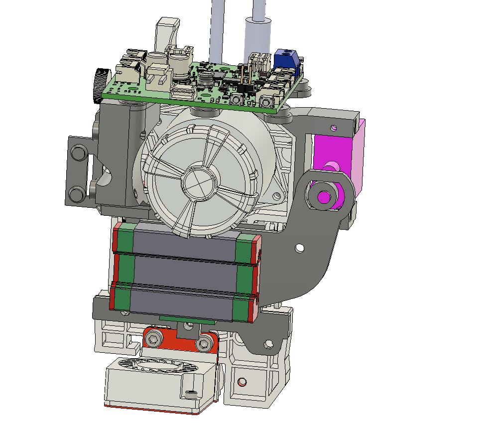
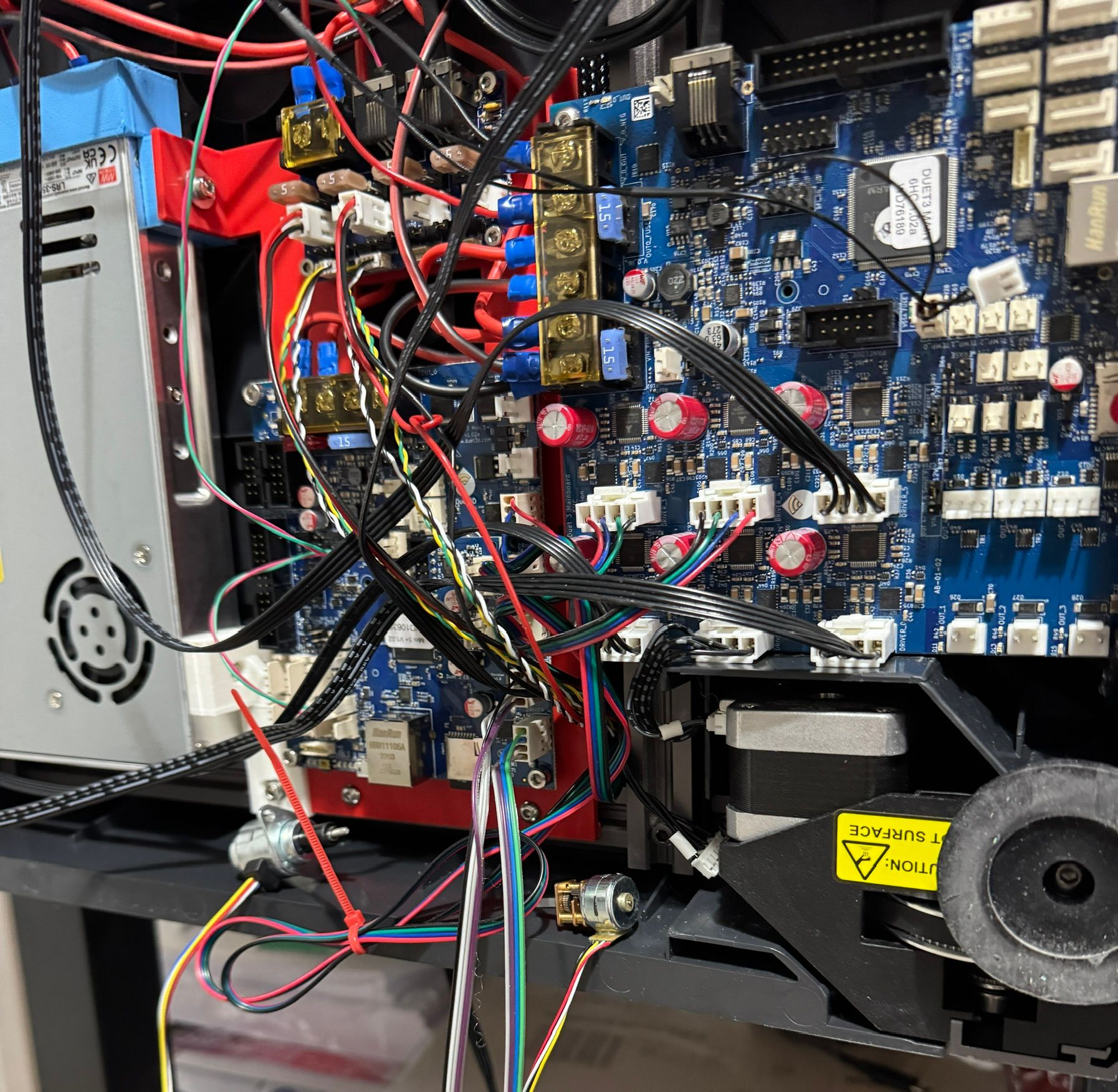
Wired up two types of z-hopper steppers - on the Mini5+ board
They both seem to move ok - but the Geared stepper looks very small and I don't have a mA rating for them - but they are only £5 from PiHut.
The linear motor seems to work quite well - but it is a bit noisy on idle - so need to investigate that.
Relevant settings below - I put them on B and C axis for now - need to adjust the steps per MM for the the smaller geared motor - as it needs about 50mm movement for the spindle to turn.
; Smart Drivers
M569 P0.0 S1 D2 ; driver 0.0 goes forwards (Z axis)
M569 P0.1 S1 D2 ; driver 0.1 goes forwards (Z axis)
M569 P0.2 S0 D2 ; driver 0.2 goes backwards (Z axis)
M569 P0.3 S1 D2 ; driver 0.3 goes forwards (X axis)
M569 P0.4 S0 D2 ; driver 0.4 goes backwards (Y axis)
M569 P0.5 S0 D2 ; driver 0.5 goes backwards (Z axis)
M569 P1.0 S0 D3 V2000 ; driver 1.0 goes backwards (U axis)
M569 P1.1 S0 D3 V2000 ; driver 1.1 goes backwards (V axis)
M569 P1.2 S1 D2 ; driver 1.2 goes forwards (A axis)
M569 P1.3 S1 D2 ; Z-hopper 1
M569 P1.4 S1 D2 ; Z-hopper 2
M569 P121.0 S0 D2 ; driver 121.0 goes backwards (extruder 0)
M569 P122.0 S0 D2 ; driver 122.0 goes backwards (extruder 1)

; Motor Idle Current Reduction
M906 I30 ; set motor current idle factor
M84 S30 ; set motor current idle timeout

; Axes
M584 X0.3 Y0.4 Z0.1:0.2:0.0:0.5 U1.0 V1.1 A1.2 B1.3 C1.4; set axis mapping
M350 X16 Y16 Z16 U16 V16 A16 B16 C16 I1 ; configure microstepping with interpolation
M906 X800 Y800 Z800 U800 V800 A800 B50 C50 ; set axis driver currents
M92 X80 Y80 Z533.33 U100 V100 A533 B629 C629 ; configure steps per mm
M208 X0:300 Y-5:295 Z0:300 U0:300 V0:300 A0:300 B0:3 C0:3 ; set minimum and maximum axis limits
M566 X12000 Y12000 Z3000 U6000 V6000 A3000 B1000 C1000 ; set maximum instantaneous speed changes (mm/min)
M203 X42000 Y42000 Z3000 U21000 V21000 A3000 B1000 C1000 ; set maximum speeds (mm/min)
M201 X500 Y500 Z20 U250 V250 A20 B20 C20 ; set accelerations (mm/s^2)
I carried on using the configuration tool for as long as I could - but it seems to keep losing the !'s on my end stops - so switched to just editing config.g.
One thing I have noticed that I really like about Duet without RPI as how quick it boots up / restarts vs how long the Klipper based board that came with the SV08 took.
Also looking forward to be able to start prints much quicker than my X1Cs - which take about 7 or 8 minutes calibration before they start anything.
Specs for smaller geared stepper (pictured on right) attached below