Mesh Bed Compensation Issue – Front Closer Than Rear
-
@cemu said in Mesh Bed Compensation Issue – Front Closer Than Rear:
but no matter what I do, the front of the bed is always closer than the rear.
Please can you confirm what you have done. Also post your heighmap.csv (or the heighmap file you are using if not the default)
-
@cemu said in Mesh Bed Compensation Issue – Front Closer Than Rear:
leadscrews at rear left, front middle and rear right
Please first check that your leadscrew couplings are tight, if that's how the motor is connected to the leadscrew, and that particularly the front Z carriage is moving freely on it's bearing, ie not getting stuck 'up'.
Do you use three-point bed levelling using the Klicky probe near the leadscrew positions before mesh levelling? Ideally you need to do this every time you turn the machine on, as the motors can jump a couple of full steps in either direction when powered up, so the bed will can be in a different position each time. See https://docs.duet3d.com/en/User_manual/Connecting_hardware/Z_probe_auto_levelling
Not a big issue (though it depends what version of RRF you are using), but the following Gcodes in your config.g can only take one parameter for X, Y, Z and U (E can take as many parameters as there are extruders):
M350 X16 Y16:16 Z16:16:16 U16 E16:16 I1                                           ; configure microstepping with interpolation
M92  X80 Y80:80 Z800:800:800 U80 E691.84:691.84              ; set steps per mm

M566 X800.00 Y300.00:300.00  Z150.00:150.00:150.00 U800.00 E900.00:900.00         ; set maximum instantaneous speed changes (mm/min)
M203 X50000.00 Y30000.00:30000.00 Z1600.00:1600.00:1600.00 U50000.00 E10000:10000 ; set maximum speeds (mm/min)
M201 X1000.00 Y750.00:750.00 Z500.00:500.00:500.00 U10000.00 E5000:5000           ; set accelerations (mm/s^2)

M906 X1800 Y1800:1800 Z1250:1250:1250 U1800 E900:900 I30                          ; set motor currents (mA) and motor idle factor in per cent
Generally, only the first parameter is used (because all motors on a multiple-motor axis must be identical). So should be:
M350 X16 Y16 Z16 U16 E16:16 I1                                           ; configure microstepping with interpolation
M92  X80 Y80 Z800 U80 E691.84:691.84              ; set steps per mm

M566 X800.00 Y300.00  Z150.00 U800.00 E900.00:900.00         ; set maximum instantaneous speed changes (mm/min)
M203 X50000.00 Y30000.00 Z1600.00 U50000.00 E10000:10000 ; set maximum speeds (mm/min)
M201 X1000.00 Y750.00 Z500.00 U10000.00 E5000:5000           ; set accelerations (mm/s^2)

M906 X1800 Y1800 Z1250 U1800 E900:900 I30                          ; set motor currents (mA) and motor idle factor in per cent
Please post what version of RRF you are using. Send M122 and post the response.
Ian
-
@T3P3Tony said in Mesh Bed Compensation Issue – Front Closer Than Rear:
Please can you confirm what you have done. Also post your heighmap.csv (or the heighmap file you are using if not the default)
Hi Tony,
Thanks for your response! Below, I’m sharing my probe repeatability test results, the latest height map, homing files, and my updated config file.
I have tried to fine-tune the x y z axis steps per mm by measuring with a micrometer to ensure accuracy, did not work thus went back to stock steps per/mm. I have tested both three-point independent Z motor bed leveling and standard spring leveling, but the issue persists in both cases. Additionally, I have tried tweaking the lead screw coordinates to compensate for any potential mechanical misalignment. The mechanical system has been carefully checked for any loose components or inconsistencies. I have also tested after allowing the machine to thermally stabilize for 30+ minutes, but the results remain the same.
@droftarts said in Mesh Bed Compensation Issue – Front Closer Than Rear:
Please first check that your leadscrew couplings are tight, if that's how the motor is connected to the leadscrew, and that particularly the front Z carriage is moving freely on it's bearing, ie not getting stuck 'up'.
Do you use three-point bed levelling using the Klicky probe near the leadscrew positions before mesh levelling? Ideally you need to do this every time you turn the machine on, as the motors can jump a couple of full steps in either direction when powered up, so the bed will can be in a different position each time.
Not a big issue (though it depends what version of RRF you are using), but the following Gcodes in your config.g can only take one parameter for X, Y, Z and U (E can take as many parameters as there are extruders):
I have inspected the mechanical system, ensuring that the lead screw couplings are tight and that all Z carriages move freely without binding. I am using three-point independent Z motor leveling, the config has been adjusted according to your suggestion. However, after applying these updates, I am now getting the warning:
"Warning: the height map has a substantial Z offset."
Let me know if you need any additional details, and I appreciate any further suggestions!
M122
=== Diagnostics ===
RepRapFirmware for Duet 2 WiFi/Ethernet version 3.5.4 (2024-11-24 10:43:42) running on Duet WiFi 1.02 or later + DueX5
Board ID: 0JD0M-9P6M2-NW4SJ-6J1F8-3SJ6M-1ASHK
Used output buffers: 17 of 26 (22 max)
=== RTOS ===
Static ram: 23488
Dynamic ram: 74988 of which 0 recycled
Never used RAM 12028, free system stack 98 words
Tasks: NETWORK(2,nWait 6,15.2%,222) HEAT(3,nWait 5,0.1%,328) Move(4,nWait 5,0.0%,274) DUEX(5,nWait 5,0.0%,18) MAIN(1,running,84.5%,742) IDLE(0,ready,0.2%,29), total 100.0%
Owned mutexes: WiFi(NETWORK)
=== Platform ===
Last reset 00:20:17 ago, cause: software
Last software reset at 2025-02-08 11:59, reason: User, Gcodes spinning, available RAM 15000, slot 0
Software reset code 0x0003 HFSR 0x00000000 CFSR 0x00000000 ICSR 0x0041f000 BFAR 0xe000ed38 SP 0x00000000 Task MAIN Freestk 0 n/a
Error status: 0x00
Aux0 errors 0,0,0
MCU temperature: min 27.4, current 29.3, max 29.9
Supply voltage: min 23.9, current 24.1, max 24.4, under voltage events: 0, over voltage events: 0, power good: yes
Heap OK, handles allocated/used 99/0, heap memory allocated/used/recyclable 2048/520/520, gc cycles 0
Events: 0 queued, 0 completed
Driver 0: standstill, SG min 0
Driver 1: standstill, SG min 0
Driver 2: standstill, SG min 0
Driver 3: standstill, SG min n/a
Driver 4: standstill, SG min n/a
Driver 5: standstill, SG min 0
Driver 6: standstill, SG min 0
Driver 7: standstill, SG min 0
Driver 8: standstill, SG min 0
Driver 9: standstill, SG min n/a
Driver 10:
Driver 11:
Date/time: 2025-02-08 12:19:44
Cache data hit count 4294967295
Slowest loop: 195.87ms; fastest: 0.17ms
I2C nak errors 0, send timeouts 0, receive timeouts 0, finishTimeouts 0, resets 0
=== Storage ===
Free file entries: 10
SD card 0 detected, interface speed: 12.0MBytes/sec
SD card longest read time 8.1ms, write time 99.4ms, max retries 0
=== Move ===
DMs created 83, segments created 5, maxWait 137624ms, bed compensation in use: none, height map offset 0.000, max steps late 0, min interval 0, bad calcs 0, ebfmin 0.00, ebfmax 0.00
no step interrupt scheduled
Moves shaped first try 0, on retry 0, too short 0, wrong shape 0, maybepossible 0
=== DDARing 0 ===
Scheduled moves 238, completed 238, hiccups 0, stepErrors 0, LaErrors 0, Underruns [0, 0, 10], CDDA state -1
=== Heat ===
Bed heaters 0 -1 -1 -1, chamber heaters -1 -1 -1 -1, ordering errs 0
Heater 0 is on, I-accum = 0.2
=== GCodes ===
Movement locks held by null
HTTP is idle in state(s) 0
Telnet is idle in state(s) 0
File is idle in state(s) 0
USB is idle in state(s) 0
Aux is idle in state(s) 0
Trigger is idle in state(s) 0
Queue is idle in state(s) 0
LCD is idle in state(s) 0
Daemon is idle in state(s) 0
Autopause is idle in state(s) 0
Q0 segments left 0
Code queue 0 is empty
=== DueX ===
Read count 39, 1.92 reads/min
=== Network ===
Slowest loop: 344.29ms; fastest: 0.00ms
Responder states: HTTP(0) HTTP(0) HTTP(0) FTP(0) Telnet(0)
HTTP sessions: 1 of 8
=== WiFi ===
Interface state: active
Module is connected to access point
Failed messages: pending 0, notrdy 0, noresp 0
Firmware version 2.2.0
MAC address e0:98:06:a4:41:ab
Module reset reason: Turned on by main processor, Vcc 3.42, flash size 4194304, free heap 31848
WiFi IP address 100.100.10.51
Signal strength -51dBm, channel 13, mode 802.11n, reconnections 0
Clock register 00002002
Socket states: 0 0 0 0 0 0 0 0
; Configuration file for Duet2 WiFi + DueX5 (firmware version 3.5.4) ; General preferences G90 M83 M550 P"X Pro" ; set printer name M575 P1 S1 B57600 ; configure PanelDue ;--------------------------------------------------------------------------------------------------------------------------------------------------------- ; Network M551 P"2845" ; set password M552 S1 ; enable network M586 P0 S1 ; enable HTTP M586 P1 S0 ; FTP M586 P2 S0 ; Telnet ;---------------------------------------------------------------------------------------------------------------------------------------------------------- ; Drives M569 P0 S0 ; physical drive 0 goes forwards M569 P1 S1 ; physical drive 1 goes forwards M569 P2 S0 ; physical drive 2 goes forwards M569 P3 S0 ; physical drive 3 goes forwards M569 P4 S0 ; physical drive 4 goes forwards M569 P5 S1 ; physical drive 5 goes forwards M569 P6 S1 ; physical drive 6 goes forwards M569 P7 S1 ; physical drive 7 goes forwards M569 P8 S1 ; physical drive 8 goes forwards M584 X0 Y1:7 Z5:2:6 U8 E3:4 ; set drive mapping M669 K0 X1:0:0:0 Y1:1:0:-1 Z0:0:1:0 U0:0:0:1 M671 X-115:245:615 Y-30:375:-30 S5 ; leadscrews at rear left, front middle and rear right M350 X16 Y16 Z16 U16 E16:16 I1 ; configure microstepping with interpolation M92 X80 Y80 Z800 U80 E691.84:691.84 ; set steps per mm M566 X800.00 Y300.00 Z150.00 U800.00 E900.00:900.00 ; set maximum instantaneous speed changes (mm/min) M203 X50000.00 Y30000.00 Z1600.00 U50000.00 E10000:10000 ; set maximum speeds (mm/min) M201 X1000.00 Y750.00 Z500.00 U10000.00 E5000:5000 ; set accelerations (mm/s^2) M906 X1800 Y1800 Z1250 U1800 E900:900 I30 ; set motor currents (mA) and motor idle factor in per cent M84 S10 ; Set idle timeout M911 S21.0 R23.0 P"M913 Z0 G91 M83 G1 X5 E-5 F1000" M950 S8 C"duex.pwm2" ;----------------------------------------------------------------------------------------------------------------------------------------------------------- ; Axis Limits M208 S1 X-64.4 Y-5 U0 Z-1 ; set axis minima M208 S0 X500 Y315 U564.98 Z400 ; set axis maxima ;----------------------------------------------------------------------------------------------------------------------------------------------------------- ; Endstops ;Sağ ön Z ye bağlı e0stop, Sol ön e1stop, arka e2stop M574 X1 S1 P"xstop" ; configure switch-type (e.g. microswitch) endstop for high end on X via pin ^xstop M574 Y2 S1 P"ystop+duex.e3stop" ; configure switch-type (e.g. microswitch) endstop for high end on Y via pin ^ystop M574 Z2 S1 P"e0stop+zstop+e1stop" ; configure active-high endstops for low end on Z via pins zstop and e1stop M574 U2 S1 P"duex.e2stop" ; configure switch-type (e.g. microswitch) endstop for high end on Z via pin ^zstop ;---------------------------------------------------------------------------------------------------------------------------------------------------------------- ; Z-Probe M558 P8 R0.5 C"zprobe.in" H2 F400 T8000 A4 X0 Y0 Z5 ; set Z probe type to effector and the dive height + speeds G31 P50 X0 Y3 Z17.55 ; set Z probe trigger value, offset and trigger height M557 X30:470 Y30:270 S30 ; probe from X=20 to 530, Y=0 to 270mm with a mesh spacing of 30mm ;------------------------------------------------------------------------------------------------------------------------------------------------------------------------ ; Heaters M308 S0 P"bedtemp" Y"thermistor" T100000 B4138 A"Bed_HEAT" M950 H0 C"bedheat" T0 M307 H0 B0 R1.184 C132.5 D3.43 S1.00 V24.2 M140 H0 M143 H0 S120 M308 S1 P"e1temp" Y"pt1000" pt1000 B4138 A"X_HEAT" M950 H1 C"e1heat" T1 M307 H1 R3.845 K0.473:0.000 D3.95 E1.35 S1.00 B0 V24.1 M143 H1 S301 M308 S2 P"e0temp" Y"pt1000" pt1000 B4138 A"U_HEAT" M950 H2 C"e0heat" T2 M307 H2 R3.845 K0.473:0.000 D3.95 E1.35 S1.00 B0 V24.1 M143 H2 S301 ;------------------------------------------------------------------------------------------------------------------------------------------------------------------------------------------------ ; Fans M950 F2 C"fan0" Q500 M106 P2 S1 H1 T40 M950 F3 C"fan1" Q500 M106 P3 S1 H2 T40 M950 F0 C"fan2" Q500 M106 P0 S0 H-1 C"X-PC" M950 F1 C"duex.fan3" Q500 M106 P1 S0 H-1 C"U-PC" M950 F4 C"duex.e4heat" Q500 M106 P4 S0 H-1 C"Chamber" M950 F5 C"duex.e5heat" Q500 M106 P5 S0 H-1 C"Static" M950 F6 C"duex.e6heat" Q500 M106 P6 S0 H-1 C"Under Bed" ;------------------------------------------------------------------------------------------------------------------------------------------------------------------------------------------------ ; Tools M563 P0 S"X" D0 H1 F0 G10 P0 X0 Y0 Z0 U0 G10 P0 R0 S0 M563 P1 S"U" D1 H2 F1 X3 G10 P1 Y0.4 U0 Z-0.05 S0 R0 G10 P1 R0 S0 ; Create a tool that prints 2 copies of the object using both carriages M563 P2 S"XU-Copy" D0:1 H1:2 X0:3 F0:1 G10 P2 X0 Y0 U-250 S0 R0 M567 P2 E1:1 M568 P2 S1 M563 P3 D0:1 H1:2 X0:3 F0:1 S"XU-Mirror" G10 P3 X0 Y0 U-500 S0 R0 M567 P3 E1:1 M568 P3 S1; bed.g ; called to perform automatic bed compensation via G32 G90 G29 S2 M561 T0 G28 G1 X372 F6000 ; Go to Klick pick up point M280 P8 S20 ; Opes servo arm G4 P1000 M280 P8 S20 ; Opes servo arm G1 Y260 F5000 ; Pick Up Klick M280 P8 S130 ; Close servo arm M400 G1 X250 Y150 Z120 F5500 ; Go to bed center G30 ; Probe onece for Z=0 G30 P0 X250 Y270 Z-99999 ; probe near a leadscrew G30 P1 X8 Y0 Z-99999 ; probe near a leadscrew G30 P2 X483 Y0 Z-99999 S3 ; probe near a leadscrew and calibrate 3 motors G30 P0 X250 Y270 Z-99999 ; probe near a leadscrew G30 P1 X8 Y0 Z-99999 ; probe near a leadscrew G30 P2 X483 Y0 Z-99999 S3 ; probe near a leadscrew and calibrate 3 motors G1 X250 Y150 F6000 ; Go to bed center G30 ; Probe onece for Z=0 G29 G1 Z120 F5000 ; Lower Bed G1 X372 Y260 F5000 ; Go to Klick pick up point M280 P8 S22 ; Opes servo arm G1 X372 Y312 F2000 ; Drop Klick G1 X322 Y312 F2000 ; Remove Klick M280 P8 S130 ; Close servo arm M400; homez.g ; called to home the Z axis M400 M400 G91 G1 H1 Z800 F15000 G1 H2 Z-5 F7500 G1 H1 Z500 F4500 G90 M400;homeall.g ; called to home all axes ;--------------------------------------------------------------------------------------------------- M400 M400 G91 G1 H1 X-505 F4000 G1 H2 X5 F9500 G1 H1 X-320.5 F4000 G90 M400 ;--------------------------------------------------------------------------------------------------- M400 G91 G1 H1 U505 F4000 G1 H2 U-5 F9500 G1 H1 U30 F4000 G90 M400 ;--------------------------------------------------------------------------------------------------- G1 X-40 U547 ;--------------------------------------------------------------------------------------------------- M400 G91 G1 H1 Y305 F4000 G1 H2 Y-5 F8000 G1 H1 Y305 F3500 G90 M400 ;--------------------------------------------------------------------------------------------------- G1 Y305 ;--------------------------------------------------------------------------------------------------- M400 G91 G1 H1 X-505 F4000 G1 H2 X5 F9500 G1 H1 X-320.5 F4000 G90 M400 ;--------------------------------------------------------------------------------------------------- M400 G91 G4 P200 G1 H1 U505 F4000 G1 H2 U-5 F9500 G1 H1 U30 F4000 G90 M400 ;--------------------------------------------------------------------------------------------------- M400 M400 G91 G1 H1 Z800 F15000 G1 H2 Z-5 F7500 G1 H1 Z500 F4500 G90 M400RepRapFirmware height map file v2 generated at 2025-02-07 21:50 min error -0.098 max error 0.176 mean 0.056 deviation 0.055 axis0 axis1 min0 max0 min1 max1 radius spacing0 spacing1 num0 num1 X Y 2.75 497.67 1.83 295.96 -1 32 32 16 10 0.022 0.017 0.051 0.052 0.046 0.066 0.128 0.091 0.171 0.124 0.106 0.107 0.134 0.121 0.114 0.078 0.005 0.027 0.087 0.056 0.081 0.072 0.119 0.134 0.13 0.119 0.069 0.11 0.084 0.076 0.077 0.064 -0.011 0.012 0.041 0.055 0.066 0.084 0.136 0.124 0.138 0.109 0.098 0.143 0.098 0.109 0.076 0.068 0.004 0.022 0.055 0.082 0.059 0.079 0.132 0.107 0.176 0.083 0.103 0.106 0.099 0.07 0.049 0.005 -0.029 -0.001 0.021 0.036 0.092 0.044 0.093 0.124 0.126 0.088 0.075 0.057 0.07 0.068 0.007 -0.081 -0.068 -0.028 -0.001 0.031 0.055 0.052 0.062 0.068 0.097 0.08 0.064 0.039 0.051 0.036 0.017 -0.066 -0.071 -0.026 -0.018 0.007 0.007 0.008 0.077 0.112 0.114 0.063 0.03 0.015 0.058 0.046 0.014 -0.041 -0.068 0.049 0.117 0.047 -0.005 0 0.086 0.105 0.129 0.089 0.051 0.012 0.048 0.049 0.046 -0.036 -0.098 -0.033 -0.01 -0.028 0.022 -0.001 0.052 0.101 0.112 0.077 0.077 0.108 0.026 0.037 0.054 -0.022 -0.053 -0.055 -0.041 -0.015 0.001 0.023 0.069 0.111 0.126 0.094 0.119 0.095 0.116 0.092 0.116 0.041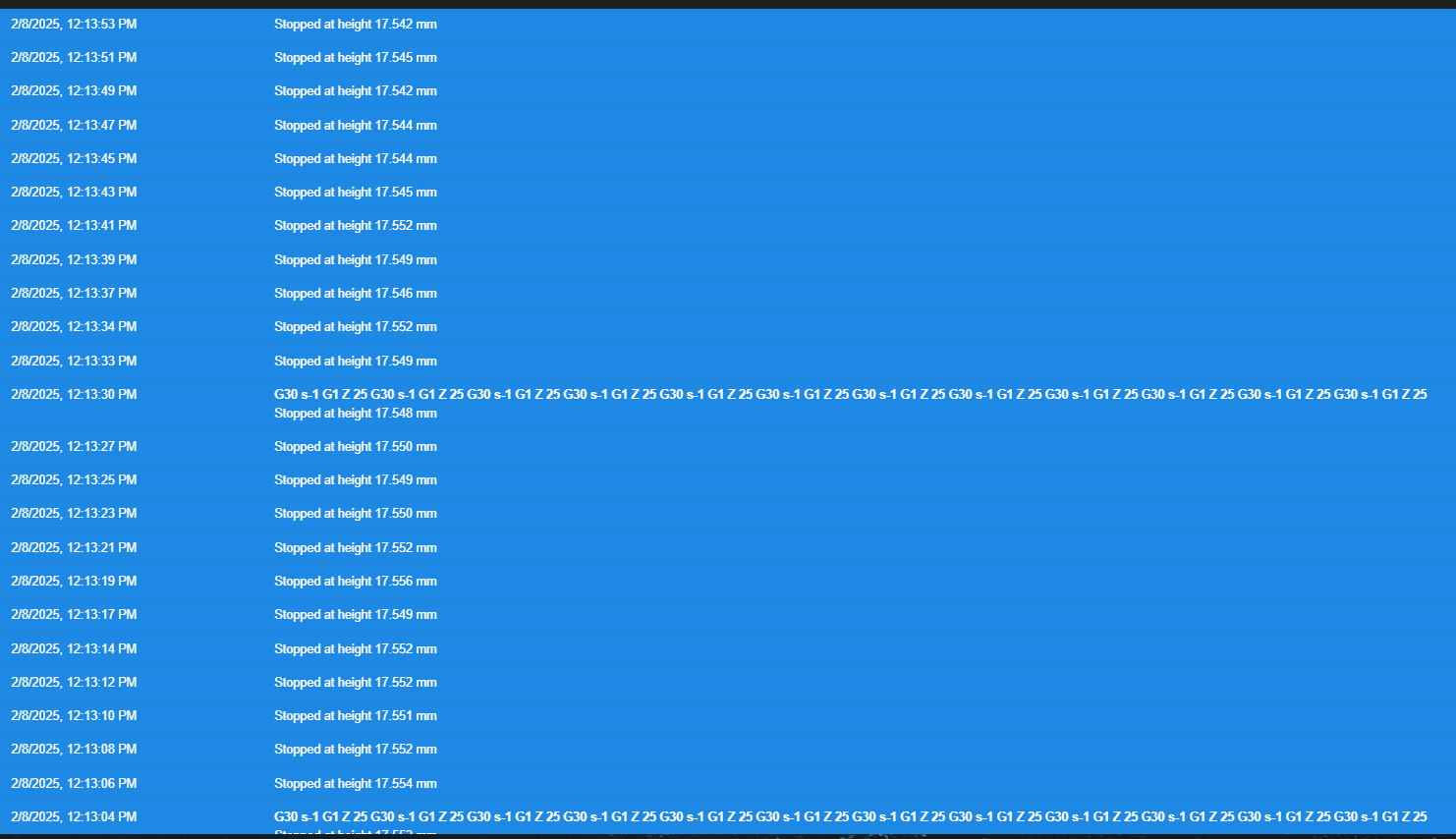
-
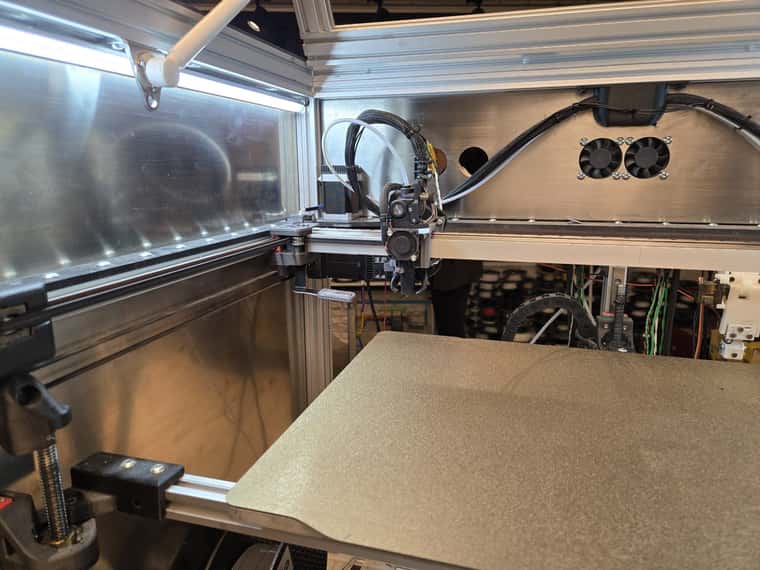
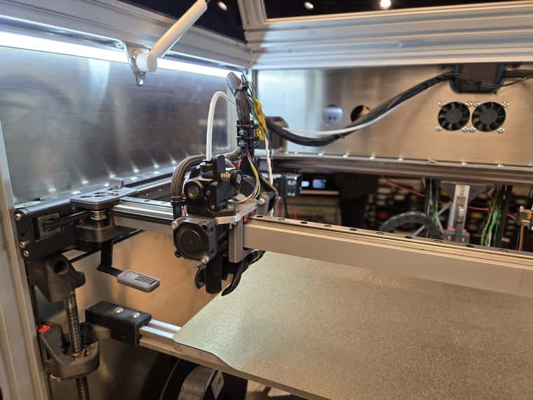
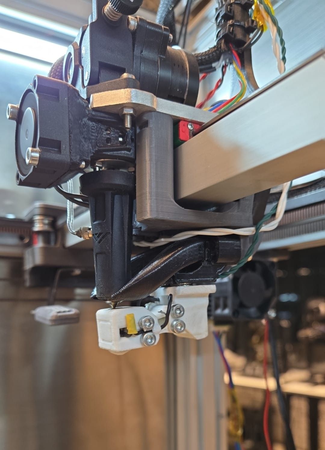
@cemu Can you post some pictures of your printer showing the print head at the "front" and "rear" of the bed?
-
@gloomyandy Of course
)
-
@cemu said in Mesh Bed Compensation Issue – Front Closer Than Rear:
However, after applying these updates, I am now getting the warning:
"Warning: the height map has a substantial Z offset."
At what point do you get this message? Usually you get this when you load a height map (G29 S1) without homing Z, or the height map was created with a large Z offset.
Your M122 reports that no bed compensation is in use ("bed comp in use: none, height map offset 0.000"):
=== Move ===
Segments created 0, maxWait 0ms, bed comp in use: none, height map offset 0.000, hiccups added 0/0 (0.00/0.00ms), max steps late 0, ebfmin 0.00, ebfmax 0.00
Though I don't know at what point you sent this M122. Check that your print file isn't cancelling bed mesh.
Ian
Bed-slinger - Mini5+ WiFi/1LC | RRP Fisher v1 - D2 WiFi | Polargraph - D2 WiFi | TronXY X5S - 6HC/Roto | CNC router - 6HC | Tractus3D T1250 - D2 Eth
-
@droftarts Hi Ian,
After applying the suggested updates, I created a new mesh from scratch, and the warning appeared immediately after the mesh was generated. I set the Z=0 datum at the center of the bed and ensured that a probe point was present at the center during mesh generation. However, the center probe point came out 0.25mm higher than expected, and the entire bed appeared to be above the 0 reference plane.
Right now, I’ve prepared a fresh config file from scratch, with triple screw adjustment disabled and even without activating the servo arm. However, I’m still seeing the same issue.
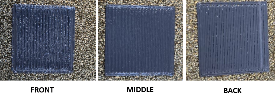
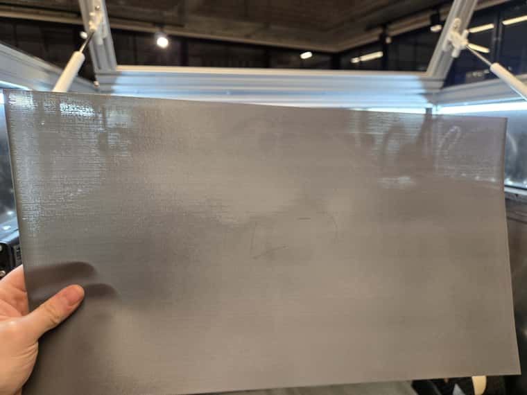
I also experimented with some slicer tweaks—setting the first layer height to 0.3mm and layer width to 0.5mm—to allow for a bit more error tolerance and improve adhesion. The squares are printing better, and while the front is still closer, the back is at least adhering now.
A full-layer test print is currently in progress, and once it’s finished, I’ll share photos of the results along with my latest home and config files.
Also, I took the M122 report right after powering on the printer. During printing, I monitored the Z motors, and they are actively moving. If I disable mesh compensation during printing, the results get significantly worse.
Thanks for your help!!
-
@cemu I generally find bed mesh height mapping is more reliable if I home Z before AND after either making the bed mesh, or loading a bed mesh. I can't quite work out if that's what you're doing! If you're finding the nozzle is too far away from the bed and you are having to baby-step, you may want to adjust the Z probe Z offset (G31 Z... in config.g).
You can also do adaptive bed mesh, ie a bed mesh only where you are going to print, before each print. This was posted recently, and there are other examples on the forum: https://forum.duet3d.com/topic/37423/adaptive-mesh-probing-script-for-prusaslicer-superslicer
Ian
Bed-slinger - Mini5+ WiFi/1LC | RRP Fisher v1 - D2 WiFi | Polargraph - D2 WiFi | TronXY X5S - 6HC/Roto | CNC router - 6HC | Tractus3D T1250 - D2 Eth
-
@droftarts Hi Ian,
In normal operation, I do use adaptive mesh, and the mesh grid is automatically generated based on the print area defined by the slicer. My bed.g file follows this sequence:
Homing all axes
Setting Z=0 datum
Lead screw adjustment
Setting Z=0 datum again
Running G29 for mesh compensation
However, I wasn't resetting Z=0 after generating the mesh, so I'll try that in my next test.I haven’t needed to apply baby stepping—the Z=0 datum point prints well. However, at that point, the mesh consistently shows a 0.2mm offset above the 0 plane. The pattern is always the same: the front is closer, and the back is farther. It feels like if the rear stepper moved slightly higher, the issue would resolve itself without modifying the mesh.
I’m sharing the latest config files, home files, and print results below. The slicer tweaks helped—the first layers initially looked great, but once removed from the bed, I noticed that on the rear corners, the solid fill wasn’t fully connecting.
Do you have any other ideas to try?
Thanks!
config.g
bed.g
homeall.g
homeu.g
homex.g
homey.g
homez.g
heightmap.csv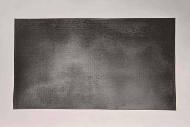
-
Hi Ian,
I tested taking Z=0 datum both before and after mesh generation, and when I do this, I end up needing to use baby stepping—I have to lower Z by at least 0.20mm for proper first-layer adhesion.
If I take Z=0 datum, generate the mesh, and then start printing immediately, a Z offset of 17.7 works well for the middle of the bed, but I still see the same issue where the front is too close and the back is too far.
However, if I take Z=0 datum, , then reload the same mesh with G29 S1 and take Z=0 again, the Z offset shifts unexpectedly.
Let me know if you have any thoughts on this!
Thanks!
-
Can you test measuring the z probe trigger height at different locations around the bed?
-
@cemu Here's the image of your bedmesh (if you have the 'Height Map' plugin enabled you can see this for yourself):

This shows a pronounced bowing of the bed, with the middle being around 0.4mm higher than the edge, and appears to get a little worse front-to-back. I think the first thing to do is to determine if it's the bed that is not flat (put a straight edge across it), or if the X axis gantry is bowed - a possibility as the X axis is long. If both appear straight, the distortion is being introduced by the X carriage sagging along the X axis travel, rotating around the X axis. This may lead to a mis-measurement of the bed from the nozzle, because the probe is offset from the nozzle. Usually we see this if the probe is offset in the Y direction, like the following image, but it could also apply with a probe in the Z direction:
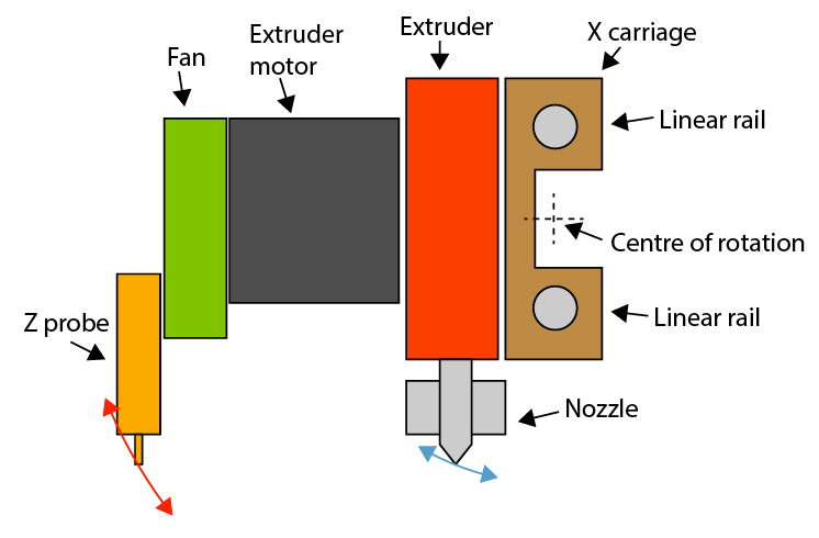
If the carriage is rotating around the X axis, you might also notice that a line extruded along the X axis exhibits a slight bow. Possible causes for this that I can think of are: loose linear carriage on the linear rail, off-centre weight distribution of X carriage, wires/filament feed pulling on the carriage, belts tilting the carriage.
You can create a mesh using the actual nozzle, by setting the probe type to 0 (M558 P0, see https://docs.duet3d.com/en/User_manual/Connecting_hardware/Z_probe_connecting#mode-0). This is a bit laborious, so don't do a mesh with too many points! But it may show up a difference between what the probe is measuring vs the Z position of the nozzle.
Ian