Need help with 5 Bar SCARA configuration
-
I guess the C80:200:100:-17 values are wrong. X actuator from 80 to 200 degrees seems ok, but 100 to -17 not. Try 0 to 150 instead. The first value of the second actuator 100 is the min value, so it would mean from 100 to 343 (360 - 17), but I don't think that the code calculates 360-17. It will deny the calculation, because min is higher than the max value. Additionally, the 100 to 343 doesn't include your desired 90 degrees. The homing positions is outside the C values, that's probably the reason for the be unreachable message.
To make it short, try e.g. C80:200:0:150
If you want to make it exact, check which areas are reachable by the endpoint with the given mode L2, and watch the possible angles, then set them.
-
@DoodleCube said in Need help with 5 Bar SCARA configuration:
little bit confused on the documentation
please tell me what you don't understand, then I will clearify it (because I am the one who wrote the documentation - and developed the kinematics).
Did you read this page? https://docs.duet3d.com/User_manual/Machine_configuration/Configuration_five_bar_parallel_scara
-
Good to see you! Yes that is the page I started from. Playing around with the config yesterday I was able to get it to home by updating the homing values. I will post an updated version of my config that sorta works to show what I have now. I can move the arm in the workspace, But after homing and jogging the arm back to center, It reads -44 on X and 99.6 on Y, when both arms should read around 45 and 135.
Also, currently moving in positive Y pulls the arm closer to the motors, and Y travel is in a skew to the left.
I did see that in the motor testing section the X motor which for me is the right motor, should turn counterclockwise when given a relative X+ movement but that seems to invert once absolute position is called.Parts of my config are below, Please let me know what im missing.
Thanks!
M92 X355.55 Y355.55 Z400 ; configure steps per mm
M208 X-60:360 Y-60:360 Z0:250 ; set minimum and maximum axis limitsM669 K9 X-32.5:32.5 Y0:0 L2 P110:110 D140:140:0:0 B200:90 C80:200:0:150 Z-180:-180:180:180 ; configure 5 Bar Parallel
M574 X1 P"xstop" S1 ; configure X axis endstop
M574 Y1 P"ystop" S1 ; configure Y axis endstop
M574 Z1 P"zstop" S1 ; configure Z axis endstop
SCARA kinematics -
@DoodleCube I have some ideas, but I am not sure whether they are correct. But you can try:
- the wrong read can be due to incorrect steps/degree calculation. Check microsteps and the gear ratio. You can measure the gear ratio by turning one wheel by 360 degree and look how much the other turns. Sometimes documentation says 1:5 and in fact its something like 1:5.18. Another possibility is slightly wrong arm length definition or some tilting of the arms (or Z movement not exactly horizontal arms). Another possibility is that home setting was not exact. The 5 bar Scara is very sensitive to exact degree reading and setting, 0.1 degrees make a big difference. This is different to linear axes, where it doesn't matter much whether the endstop is slightly wrong (with the exception of eg polar kinematics, where the calculation depends on the true absolute position. But cartesian/CoreXY, it can be slightly wrong).
- when motors are moving in unexpected directions, in most cases it is a wrong stepper direction setting. Just reverse it (M569 S parameter). Your steppers are pointing down, so you need to reverse, compared to the normal usage. When using wrong settings, I also had some very strange behaviour, e.g. different results when using absolute or relative movements. You can verify that absolute and relative movements are behaving correctly both.
- the M92 settings are steps/degree for rotational axes, I've made a few examples. You can see the controller values of the position by calling M114, they are the values in section Count.
Hope this helps.
-
@DoodleCube said in Need help with 5 Bar SCARA configuration:
I have since swapped the X actuator to the right side following some clues on other forums.
and
M669 K9 X0:65 Y0:0 ...This seems wrong to me; it looks like the kinematics expect the X actuator on the left. You have yours aligned at Y0, but offset in X. If there's 65mm between them, I would have thought this would be correct:
M669 K9 X0:0 Y65:0 ...From the wiki page:
Xnnn:mmm and Ynnn:mmm X and Y coordinates of the left and right proximal actuator axes. E.g. X0:100.5 Y0:0 means 100.5 apart and both on the y axis.
I assume nnn and mmm are the x and y coordinates of the motor.
Edit (again): It does mean that the origin X0 Y0 is on the centre of the X motor. Maybe
M669 K9 X-32.5:0 Y32.5:0 ...would put the origin between them.Ian
TronXY X5S with Duet 3 MB6HC and Roto toolboard : Cartesian bed-slinger with Duet 3 Mini 5+ WiFi and 1LC : RRP Fisher Delta v1 with Duet 2 Maestro : Polargraph with Duet 2 WiFi
-
@JoergS5 for standard scara I seem to remember that H2/ direct motor moves happen in degrees (because if you command a single motor directly you can't command any position as with cartesian). Is that true for 5bar scara as well?
-
@oliof said in Need help with 5 Bar SCARA configuration:
H2/ direct motor moves happen in degrees
you're right. This may explain my strange experiences.
-
@droftarts said in Need help with 5 Bar SCARA configuration:
looks like the kinematics expect the X actuator on the left
the X parameter is for the first and second actuator's X coordinates, Y for the Y. In the documentations example: "E.g. X0:100.5 Y0:0 means 100.5 apart and both on the y axis." makes it clear. But this may be an example of confusing documentation...
The first actuator should be on the left. Otherwise some details like numbering of the work modes will be wrong.
@DoodleCube Stepper orientation: the definition is the axes are pointing out from the plane to you and then positive degrees are a rotation counterclockwise. So with H2 single actuator relative movement, a positive rotation must be counterclockwise. e.g. G91 G1 H2 X5 should rotate the first actuator counterlockwise by 5 degrees. Best start with small values and when you have confidence, use a value where you see whether the steps/degrees are correct, e.g. with a 90 degree rotation.
-
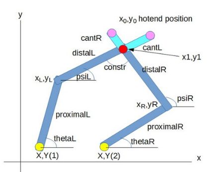
@JoergS5 Ah, right. I assumed from this image that Xnnn:mmm was the xy position of the X (or (1)) motor, and Ynnn:mmm was the position of the Y (or (2)) motor, from this diagram:
Ian
-
Quick update! It works! It looks like my issue was with my external drivers. For some reason despite them being also set to 64 microstep I had to cut the steps per mm in half. I have since moved the working arm to its own electronics and it is now running on RRF 3.4.6. I had initially wished to run this on the latest release, but it seems RRF3 on Duet 2 stopped supporting 5 bar kinematics to save space for new features.
Since this is the case, Im hoping to run across some documentation on how to import/disable kinematic binaries to these boards for future-proofing my new project.
-
@DoodleCube said in Need help with 5 Bar SCARA configuration:
it seems RRF3 on Duet 2 stopped supporting 5 bar
there are flags in RRF to turn on or off those "exotic" kinematics, so if you're able to compile it yourself, you can turn it on for Duet 2.
Pins.h
'# define SUPPORT_FIVEBARSCARA 0
Set this to 1.