Spirograph emulator with Duet2
-
Hi guys,
after seeing a super cool video of a coffetable with a carved spirograph pattern, I want to build a CNC version in smaller scale. I found a different version with external gears, I want to emulate with geared steppers:
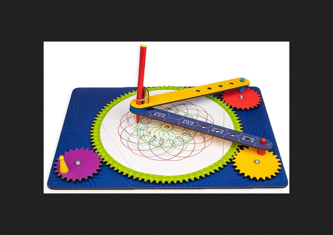
It almost looks like a 5-bar SCARA, but the motors moving the arms work with continuous rotation.
I thought of using the extruder mixing ratio for all three motors to get the typical spiro-patterns.But maybe there is a better solution to go beyond the spiro-world?
-
@o_lampe setting them up as a single mixing extruder should work. You may possibly get some rounding error resulting in the final pen position not quite lining up with the initial position. If that happens then I suggest you configure them as axes instead.
When I was a teenager I produced spirograph patterns on the screen of an old TV using two oscillators feeding modified audio amplifiers that drove the deflection coils of the CRT.
Duet WiFi hardware designer and firmware engineer
Please do not ask me for Duet support via PM or email, use the forum
http://www.escher3d.com, https://miscsolutions.wordpress.com -
@dc42 said in Spirograph emulator with Duet2:
the final pen position not quite lining up with the initial position
Depending on how good the build will be, it will look wobbly anyway. Especially the joints and wrist bearings are giving me an headache. I want to use a Dremel grinder at least...
I thought of replacing the circular motion of the two arms with ballscrews going back and forth.
IMHO, the pattern is mostly related to different starting positions ( or different start-angles in the original toy-mechanic)But how could I mimic a sinusodial motion with a linear axis?
Do we have "s-curve" acceleration? -
@o_lampe said in Spirograph emulator with Duet2:
But how could I mimic a sinusodial motion with a linear axis?
You would need to generate small segments of GCode that move the linear axes in a sinusoidal manner.
@o_lampe said in Spirograph emulator with Duet2:
Do we have "s-curve" acceleration?
Experimental S-curve acceleration is under development, but I don't believe it will help in this case,
-
At work I started building a spirograph machine based on bicycle parts similar to this:

I then began to work out the basic math behind the pattern, which I now regret not have done earlier.
Turns out, the outer toothcount should better be a binary number. That way only the small sprockets define the number of revolutions to complete a pattern.
My chain counts 124 teeth, which leads to 31 * n revolution patterns.
I'd grind a wooden surface to dust...especially at the center.Good thing, the emulated CNC version can have any number of teeth. Plus I can vary the arm lengths and emulate non_circular sprockets.
If you're interested, there is this nice spirograph simulator. Just hit the demo button and get hypnotized

-
@o_lampe I saw this video the other day, not much left in the centre! https://youtu.be/zW5nZ0Hp95k
Ian
Bed-slinger - Mini5+ WiFi/1LC | RRP Fisher v1 - D2 WiFi | Polargraph - D2 WiFi | TronXY X5S - 6HC/Roto | CNC router - 6HC | Tractus3D T1250 - D2 Eth
-
@droftarts That was the vid that got me started. All the 3D printed parts must have taken a long time...
and I thought: bike-parts?! Another guy had the same idea a while ago. It's a good starting point but not CNC-able.
The version I posted above is a better candidate. It could even work as a FDM printer.
Like a short range 5-bar SCARA with a rotary bed. I wonder if RRF supports such weird kinematics? -
@o_lampe See MakersMuse latest video where he converts rotary motion to linear motion to sine wave using a Scotch Yoke.
https://www.youtube.com/watch?v=wko3SWiV1DM
Not sure if it will be useful for you but might inspire some ideas.
-
@tas Quite the eye-opener! Thanks for posting.
I always thought that a crankshaft would create a sine wave. Now checking the above double-crank again, I'm sure the toolhead will draw an even weirder curve.Maybe I should invest some time and try to simulate it?
Would OpenScad be able to do it, or do I have to learn Blender or the like? -
@o_lampe OpenSCAD might be able to do it.
This link has an example file but it would require a lot of changes to simulate the Scotch Yoke.
https://www.instructables.com/Animating-with-OpenSCAD/
You can download their example at the bottom of the page.
-
@o_lampe I built a corexy sand table that draws patterns in baking soda "sand". Patterns are generated with Sandify. Sandify produces g-code files. My table uses a Duet2 WiFi board with an expansion board to drive two Chinese servomotors (but steppers work fine if going slow is acceptable). The servos can move the ball up to 2000 mm/sec the way I built it, but could go even faster with small changes. Many patterns have a lot of motion along the edges of the drawing space, so I use a Perl post processor that makes the Sandify pattern files run at two speeds, a relatively low speed for the actual drawing, and a high speed for the edge motion.
Sandify can also generate patterns for round tables that use rho/theta coordinates.


-
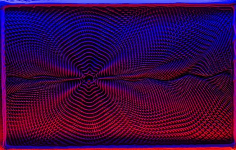
@mrehorstdmd These pics are amazing! But they are the result of pushing sand around and back, over and over again.
I'm not sure if it would look as good with a dremel?
Maybe if I use a thick layer of wooden dust and later fix it with clear epoxy?Nevertheless, it would require a known kinematic for RRF to reproduce those sandify patterns.
Right now I only have a mixing tool that moves three motors monotonously...
I think, I try wooden dust with steelball and magnet and see if it behaves sandy-like -
@o_lampe What are you actually trying to do? Are you planning to mill groves into wood or plastic?
Sandify gives a preview of what the pattern will look like, but not the way the sand piles up- just the path the ball follows:

That might give a better idea of what a groove carved into wood or plastic would look like. The pattern starts at the green dot and ends at the red dot. You can sort of control the placement of the start and finish points with the Sandify UI, but can also edit the gcode to move them as needed, within certain limitations.
-
@mrehorstdmd said in Spirograph emulator with Duet2:
What are you actually trying to do?
Good question.
If it's confirmed that Sandify's polar code is supported by RRF, I'd like to build a polar laser engraver or light grinder. (infinite rotation required and supported?)
It's definitely a step up and even easier to build than the SCARA-like dual arm, shown in my opening post.
I spent the whole Sunday afternoon watching your Arrakis playlist and then played with the polar version of Sandify. I created some interesting and doable patterns. Even some basic wiper pattern have their charm.
The fractal spirograph algorythm doesn't seem to produce the same patterns as the original, but much more complex and mesmerizing images. -
I've generated a testfile with Sandify for a polar machine. But the file looks like classic cartesian coordinates with 0,0 at the bottom/left end instead of center.
Is RRF able to digest that on a polar bed?<edit> according to the Wiki XY-offset is not supported yet
Is it possible to use a G1.1 macro instead which does the post processing on the fly?; ; File name: 'PolarSandify' ; File type: gcode ; G1 X117.776 Y111.451 G1 X87.768 Y122.172 G1 X67.855 Y95.324 G1 X88.664 Y67.022 G1 X123.451 Y78.957 G1 X122.412 Y117.191 G1 X84.209 Y127.838 G1 X62.033 Y93.102 G1 X89.794 Y60.376 G1 X130.841 Y77.746 G1 X126.383 Y123.577 G1 X79.901 Y133.128 G1 X56.414 Y90.128 G1 X91.762 Y53.782 G1 X138.485 Y77.431 G1 X129.625 Y130.544 G1 X74.879 Y137.970 G1 X51.070 Y86.420 G1 X94.566 Y47.321 G1 X146.295 Y78.037 G1 X132.081 Y138.024 G1 X69.184 Y142.294 G1 X46.072 Y82.003 G1 X98.194 Y41.072 G1 X154.184 Y79.584 G1 X133.701 Y145.943 G1 X62.864 Y146.034 G1 X41.488 Y76.908 G1 X102.629 Y35.115 G1 X162.063 Y82.081 G1 X134.440 Y154.223 G1 X55.972 Y149.130 G1 X37.386 Y71.172 G1 X107.846 Y29.527 G1 X169.842 Y85.534 G1 X134.258 Y162.782 G1 X48.566 Y151.522 G1 X33.828 Y64.837 G1 X113.815 Y24.386 G1 X177.429 Y89.936 G1 X133.125 Y171.536 G1 X40.709 Y153.160 G1 X30.874 Y57.950 G1 X120.498 Y19.763 G1 X184.735 Y95.276 G1 X131.016 Y180.395 G1 X32.470 Y153.995 G1 X28.579 Y50.565 G1 X127.851 Y15.730 G1 X191.671 Y101.533 -
@o_lampe said in Spirograph emulator with Duet2:
according to the Wiki XY-offset is not supported yet
For polar kinematics, that is correct. However, you can use workplace coordinate offsets to adjust the position. See the G10 command with the L2 or L20 parameter.
-
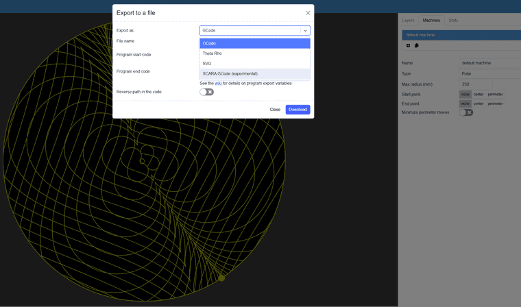
@o_lampe I've been thinking about building a machine that uses the sandify generated patterns to move a spinning abrasive head to do fancy engine-turning on metals.
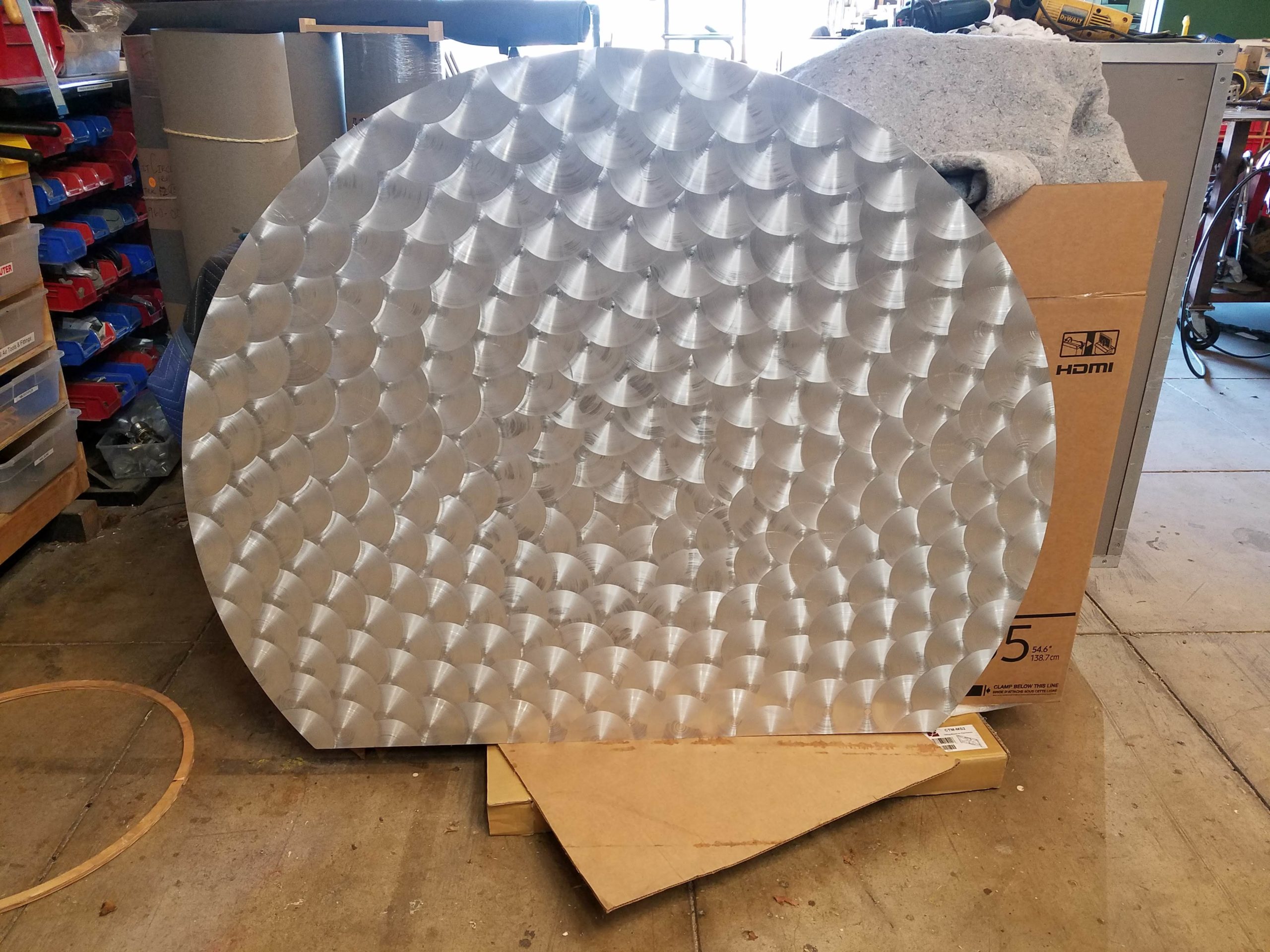
You can export the sandify patterns in different formats:
-
@mrehorstdmd My understanding is, when using polar printer kinematics, RRF internally converts regular gcode (XY based moves) into theta/rho values.
Brushed metal always looks great, but wouldn't it kill the brush, when it moves sideways while pressed on the sheet?
Guess what?!
My Boss has seen your Arrakis videos and now I have to build a sand table first
-
@o_lampe I would build the machine and alter the sandify patterns using a post processor, to press the spinning abrasive down and lift it up again at specified or calculated distances as it follows the pattern. But, it might also be create an interesting finish to drag it around while it is spinning against the metal.
There are abrasive "sticks" made for engine turning operations that wear away as they are used. They provide a consistent scratch size by controlling the diameter of the diamonds or other abrasive stones embedded in the stick. See: https://www.cratex.com/engine-turning-sticks
Are you going to use servomotors or steppers?
-
@mrehorstdmd said in Spirograph emulator with Duet2:
Are you going to use servomotors or steppers?
For the sand table my Boss donored a 60x40 window panel. It's the double walled/vacuum type.
I drilled a hole between the glass sheets and could fit a10mm steelball.
With a size like that, I guess steppers will do.
Fitting LED strips will be like building a bottle-ship, but without illumination it'll look dull.When I build an engraving polar machine later, it'll need strong motors. I think I use my favoured hoverboard BLDC motor with simpleFOCs step/dir interface.