Duet3D Logo Duet3D
    • Tags
    • Documentation
    • Order
    • Register
    • Login

    Laser wiring?

    Scheduled Pinned Locked Moved
    Duet Hardware and wiring
    6
    26
    5.5k
    Loading More Posts
    • Oldest to Newest
    • Newest to Oldest
    • Most Votes
    Reply
    • Reply as topic
    Log in to reply
    This topic has been deleted. Only users with topic management privileges can see it.
    • keyz182undefined
      keyz182
      last edited by

      @resam thanks 🙂

      I wasn't sure how to wire up the 1a,b inputs, but you've cleared that up for me!

      1 Reply Last reply Reply Quote 0
      • keyz182undefined
        keyz182
        last edited by

        0_1530960731068_Schematic_laserpwmduet_Sheet-1_20180707115047.png

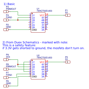
        Does #1 in the image look correct? Also, would #2 work? It was taken from the power mosfet drivers from the Duex boards (there's also a cap between 5V and GND I missed out).

        I tried #2, because I figured but it seems the laser off on 0 and 100%, and on full everywhere between.

        I can try #1, but want to make sure it's correct this time before wiring it up.

        1 Reply Last reply Reply Quote 0
        • resamundefined
          resam
          last edited by

          I'm using #1, but with the HEATER_3 pin, if I remember correctly.
          Not sure how FAN2- behaves in this circuit...

          keyz182undefined 1 Reply Last reply Reply Quote 0
          • keyz182undefined
            keyz182 @resam
            last edited by

            @resam D'oh, Looks like I got turned around - Will try on heater now.

            1 Reply Last reply Reply Quote 0
            • resamundefined
              resam
              last edited by

              On my system:

              M452 P3 to enable "laser mode" on heater 3.
              M3 S1 turn on the laser at the lowest intensity.
              M3 S255 at full intensity.
              M5 and M3 S0 is laser off.

              1 Reply Last reply Reply Quote 0
              • keyz182undefined
                keyz182
                last edited by

                It works! I think I'm going to have to write this up later and put it up here/on the wiki for others to reference. @dc42 is there any downside to using circuit #2 in my previous reply above vs the "simpler" one? If not, I'll stick with #2.

                @resam said in Laser wiring?:

                On my system:

                M452 P3 to enable "laser mode" on heater 3.
                M3 S1 turn on the laser at the lowest intensity.
                M3 S255 at full intensity.
                M5 and M3 S0 is laser off.

                Yup, that's what I've got now 🙂

                1 Reply Last reply Reply Quote 0
                • dc42undefined
                  dc42 administrators
                  last edited by

                  We use circuit #2 In the heater wiring, because users occasionally short +3.3V to ground because of incorrect endstop wiring or other reasons, and when that happens we don't want all the heaters to turn on at full power. The same considerations apply to a laser, so I suggest circuit #2.

                  Duet WiFi hardware designer and firmware engineer
                  Please do not ask me for Duet support via PM or email, use the forum
                  http://www.escher3d.com, https://miscsolutions.wordpress.com

                  keyz182undefined 1 Reply Last reply Reply Quote 0
                  • keyz182undefined
                    keyz182 @dc42
                    last edited by

                    @dc42 Great, that's what I went with, and it works 🙂

                    Thanks all for the help. I've got a bunch of cable management to do today, and once that's done, the real testing will begin. If the tests all work, I'll write it up and post it here for some vetting, and if it looks good, I (or someone) can put it up on the wifi 🙂

                    1 Reply Last reply Reply Quote 1
                    • keyz182undefined
                      keyz182
                      last edited by

                      Prepping the documentation here - https://gist.github.com/keyz182/34601ec4ba4a19c55a177d0d1738d5a3

                      Any notes or corrections welcome. Once done and peer-reviewed I'll get it moved to the wiki.

                      1 Reply Last reply Reply Quote 0
                      • resamundefined
                        resam
                        last edited by

                        Nice!

                        I think you got the GND and V_IN connection mixed up on the LASER_OUT header...?

                        keyz182undefined 1 Reply Last reply Reply Quote 0
                        • keyz182undefined
                          keyz182 @resam
                          last edited by

                          @resam Good catch, fixed 🙂

                          1 Reply Last reply Reply Quote 0
                          • keyz182undefined
                            keyz182
                            last edited by

                            Just realised I selected the 74HCT02D, rather than the 74HCT02. It's datasheet claims it's both TTL and CMOS compatible.

                            I ordered a few boards from JLPCB because I've never done board design before, and figured this would be a good start.

                            I think it should work, as the output is dependent on VCC rather than anything else, and other than also having CMOS input compatibility, it seems the same. Can someone with more knowledge in electronic weigh in to say if it's a choice that'll work, or if I need to change it?

                            T3P3Tonyundefined 1 Reply Last reply Reply Quote 0
                            • T3P3Tonyundefined
                              T3P3Tony administrators @keyz182
                              last edited by T3P3Tony

                              @keyz182 said in Laser wiring?:8

                              74HCT02D

                              should be fine, the datasheet shows the "D" to mean its SIOC foot print. What determines the logic levels is the HC/HCT (74HC02 vs 74HCT02)

                              https://en.wikipedia.org/wiki/7400_series#7400_series_derivative_families

                              www.duet3d.com

                              keyz182undefined 1 Reply Last reply Reply Quote 0
                              • keyz182undefined
                                keyz182 @T3P3Tony
                                last edited by

                                @t3p3tony Awesome, thanks.

                                Do you think the "Circuit operational theory" section I just added looks correct? I want to make sure people are able to understand why they're doing something, not just that they should do it.

                                https://gist.github.com/keyz182/34601ec4ba4a19c55a177d0d1738d5a3

                                T3P3Tonyundefined 1 Reply Last reply Reply Quote 0
                                • T3P3Tonyundefined
                                  T3P3Tony administrators @keyz182
                                  last edited by

                                  by connecting the heater PWM to two input pins of the 74HCT02, we get an inversion of the PWM, such that when PWM out is pulled low, the 74HCT02 output is driven high.

                                  This is a little confusing as written because the diagram shows PWM connected to only one input. maybe re-order the text so it is clear what the 3.3V is doing first?

                                  www.duet3d.com

                                  keyz182undefined 1 Reply Last reply Reply Quote 0
                                  • keyz182undefined
                                    keyz182 @T3P3Tony
                                    last edited by

                                    @t3p3tony rearranged slightly now - https://gist.github.com/keyz182/34601ec4ba4a19c55a177d0d1738d5a3

                                    I still haven't been able to fully test this yet, I ran out usable filament to print a cable chain mount (I have ABS, but needed to use the room today).

                                    Hopefully I'll get things all tested tomorrow, and can augment the guide with some examples of using e.g. Inkscape to do both vector and raster.

                                    1 Reply Last reply Reply Quote 1
                                    • keyz182undefined
                                      keyz182
                                      last edited by

                                      Added to the wiki - https://duet3d.dozuki.com/Item/Using_a_PWM_driven_laser_module

                                      T3P3Tonyundefined 1 Reply Last reply Reply Quote 0
                                      • T3P3Tonyundefined
                                        T3P3Tony administrators @keyz182
                                        last edited by

                                        @keyz182 thanks, I moved it to a wiki page as it's not really an item:

                                        https://duet3d.dozuki.com/Wiki/Laser_PWM_control

                                        www.duet3d.com

                                        1 Reply Last reply Reply Quote 0
                                        • keyz182undefined
                                          keyz182
                                          last edited by

                                          Can anyone recommend the best way to protect the signal from interference. The signal cable is running a total of about 1 meter alongside stepper cabling. I could run the cable separately, but would prefer to keeps it clean and together if possible.

                                          I have plenty of shielded Cat5e/6 lying about, would that be fine? How best would I go about utilising the twisted pairs? Tie them together and treat the entire cable as 4 conductors, or e.g. pair signal and gnd? Or should I just experiment and see what works?

                                          Also, does anyone have experience using Cat5e/6 for the steppers? I'd need to check the gauge on the stuff I have, but from what I've read it should be able to handle the NEMA17s I've got.

                                          1 Reply Last reply Reply Quote 0
                                          • First post
                                            Last post
                                          Unless otherwise noted, all forum content is licensed under CC-BY-SA