Beginner Needs Help - Anycubic Kossel Plus + Duet WiFi -- HOW?
-
I've decided to stick with my original rods since before i undertook the upgrade, the machine was printing good, 20 mm calibration cubes printed within 0.1 mm deviation, so i guess the small difference in that one rod isn't enough to make a huge difference in print quality.
What would make a huge difference is the 3mm difference in rod spacing between effector and carriages that i didnt notice during the upgrade!! I upgraded to robotdiggs carriages and they have 20mm spacing while the anycubic effector has 43mm. I spent 2 days scratching my head over why i couldn't get good calibration even though everything seemed to be within good tolerance. Then I realized that i never measured the effector. Luckily i have a spare one that does have 40mm spacing and now i can use my V6 without any modifications...although i do lose 37mm in build height. Anyway, first calibration with new effector got me 0.031 deviation, and that's without a probe. Now, on to the minor things so i can get printing again.
Stick with it mindbender, you'll get yours running well too! -
-
@juice said in Beginner Needs Help - Anycubic Kossel Plus + Duet WiFi -- HOW?:
I've decided to stick with my original rods since before i undertook the upgrade, the machine was printing good, 20 mm calibration cubes printed within 0.1 mm deviation, so i guess the small difference in that one rod isn't enough to make a huge difference in print quality.
Deviation is part of the story. Here's another part:
Bottom is stock AKL rods. Top is Haydn magnetic. Otherwise identical. Even same G-Code file.
Middle is a different experiment, not relevant to this discussion.

-
@danal The parts that i printed before i started my upgrade weren't as good as your top print but were much better than your bottom print, even better than the middle one. That was with the old trigorilla board, i have yet to do any prints with the duet. That said, i am sure that having those sweet magnetic arms would be beneficial, its just that if i can get good quality prints with the arms i have, i'll hold off on the upgrade until i have some money burning a hole in my pocket.

Ok, made my first print with the duet upgraded anycubic kossel. Looks pretty good to me. X & Y dimensions need tweaking though.

-
So more weird results.
I've attached the DC42 IR Sensor to the hot-end (effector?) and connected the sensor to the Duet following the instructions. I've changed my M558 P-value to P1 and followed the first half of the instructions on David's webpage for the IR sensor (Link).
-
If I put an object right near the bottom of the sensor, the LED lights up solid. I take my hand away, the LED turns off. Nice.
-
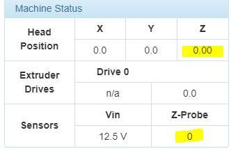
On the Duet device webpage, the Z-Probe value remains at a value of 280 no matter what the Z-height is. It fluctuates between 279-280, and that's it.
-
With 12V power applied, I enter M558 P1 then I enter G31 P500 Z1.0 on the G-Console. After setting the Z-height manually with 2 sheets of paper, I raise the nozzle 5mm up as instructed, then G92 Z0 to set Z=0.
-
Following the instructions, I enter G30 S-1 and the nozzle buries itself into the bed again HARD. Here's a screenshot of the Console:

- If I press "Home All" the assembly raises itself up to the top but doesn't click the end-stops. I then get an error:
G28
Error: G0/G1: insufficient axes homed
Error: Homing failed
Here's the config files:
- config-override.g (I commented the weird values out again):
; This is a system-generated file - do not edit ; Delta parameters ;M665 L271.000 R152.869 H301.792 B85.0 X6.799 Y4.280 Z0.000 ;M666 X2.286 Y-0.607 Z-1.679 A0.00 B0.00 ; Heater model parameters M307 H0 A90.0 C700.0 D10.0 S1.00 V0.0 B1 M307 H1 A340.0 C140.0 D5.5 S1.00 V0.0 B0 M307 H2 A340.0 C140.0 D5.5 S1.00 V0.0 B0 M307 H3 A340.0 C140.0 D5.5 S1.00 V0.0 B0 M307 H4 A340.0 C140.0 D5.5 S1.00 V0.0 B0 M307 H5 A340.0 C140.0 D5.5 S1.00 V0.0 B0 M307 H6 A340.0 C140.0 D5.5 S1.00 V0.0 B0 M307 H7 A340.0 C140.0 D5.5 S1.00 V0.0 B0- config.g:
; Configuration file for Duet WiFi (firmware version 1.20 or newer)
; executed by the firmware on start-up
;
; generated by RepRapFirmware Configuration Tool on Sun May 13 2018 19:16:40

; General preferences
G90					; Send absolute coordinates...
M83					; ...but relative extruder moves
M555 P1					; Set firmware compatibility to look like RepRapFirmare

;*** The homed height is deliberately set too high in the following - you will adjust it during calibration.
M665 R134 L270 B85 H285		; Set delta radius, diagonal rod length, printable radius and homed height
M666 X0 Y0 Z0			; Put your endstop adjustments here, or let auto calibration find them

; Network
M550 Pduettest
M552 S1					; Enable network
M586 P0 S1				; Enable HTTP
M586 P1 S0				; Disable FTP
M586 P2 S0				; Disable Telnet

; Z-Probe
M558 P1 X0 Y0 Z0 H5 F1000 T5000 ;I1 		; Set Z probe type to DC42 and the dive height + speeds
G31 X0 Y0 Z1.0 P500				; Set Z probe trigger value, offset and trigger height
M557 R130 S20					; Define mesh grid

; Drives
M569 P0 S1					; Drive 0 goes forwards
M569 P1 S1					; Drive 1 goes forwards
M569 P2 S1					; Drive 2 goes forwards
M569 P3 S1					; Drive 3 goes forwards
M350 X16 Y16 Z16 E16 I1				; Configure microstepping with interpolation
M92 X80 Y80 Z80 E96				; Set steps per mm
M566 X1200 Y1200 Z1200 E1200			; Set maximum instantaneous speed changes (mm/min)
M203 X18000 Y18000 Z18000 E1200			; Set maximum speeds (mm/min)
M201 X1000 Y1000 Z1000 E1000			; Set accelerations (mm/s^2)
M906 X1000 Y1000 Z1000 E800 I30			; Set motor currents (mA) and motor idle factor in per cent
M84 S30						; Set idle timeout

; Axis Limits
M208 Z0 S1					; Set minimum Z

; Endstops
M574 X2 Y2 Z2 S1				; Set active high endstops

; Heaters
M305 P0 T100000 B4267 C0 R4700			; Set thermistor + ADC parameters for heater 0
M143 H0 S120					; Set temperature limit for heater 0 to 120C
M305 P1 T100000 B4267 C0 R4700			; Set thermistor + ADC parameters for heater 1
M143 H1 S275					; Set temperature limit for heater 1 to 275C

; Fans
M106 P0 S0.3 I0 F500 H-1 ; Set fan 0 value, PWM signal inversion and frequency. Thermostatic control is turned off
M106 P1 S1 I0 F500 H1 T45 ; Set fan 1 value, PWM signal inversion and frequency. Thermostatic control is turned on
M106 P2 S1 I0 F500 H1 T45 ; Set fan 2 value, PWM signal inversion and frequency. Thermostatic control is turned on

; Tools
M563 P0 D0 H1					; Define tool 0
G10 P0 X0 Y0 Z0					; Set tool 0 axis offsets
G10 P0 R0 S0					; Set initial tool 0 active and standby temperatures to 0C

; Automatic saving after power loss is not enabled
M501
; Custom settings are not configured
homedelta.g:
; homedelta.g
; called to home all towers on a delta printer
;
; generated by RepRapFirmware Configuration Tool on Sun May 13 2018 19:16:40

G91                        ; relative positioning
G1 S1 X290 Y290 Z290 F1800 ; move all towers to the high end stopping at the endstops (first pass)

G1 X-5 Y-5 Z-5 F1800 S2    ; go down a few mm
G1 S1 X10 Y10 Z10 F360     ; move all towers up once more (second pass)
G1 Z-5 F6000               ; move down a few mm so that the nozzle can be centred
G90                        ; absolute positioning
;G1 X0 Y0 F6000            ; move X+Y to the centre
Entering the command "G30 S-1" is hanging me up. I've tried to do an auto-calibration and the nozzle took a number of measurements in the air above the bed ranging from 3mm - 130mm.
Can anyone make sense of this? I have not resolved the bed angle issue yet, but this is something else entirely. Please help! Thanks!
-
-
@mindbender9 said in Beginner Needs Help - Anycubic Kossel Plus + Duet WiFi -- HOW?:
On the Duet device webpage, the Z-Probe value remains at a value of 280 no matter what the Z-height is. It fluctuates between 279-280, and that's it.
That suggests that either you have connected the OUT pin of the IR sensor to the wrong pin, or there is a bad connection in that wire. It should be connected to the pin labelled IN on the Probe connector. That's the pin on the opposite end of the connector to the 3.3V pin.
Duet WiFi hardware designer and firmware engineer
Please do not ask me for Duet support via PM or email, use the forum
http://www.escher3d.com, https://miscsolutions.wordpress.com -
Also, homing MUST work before anything else.
homedelta.g should have much larger values in the first G1 command larger than the physical printer, so that the carriages go all the way to the switches, something like
G1 S1 X400 Y400 Z400 F1800Delta / Kossel printer fanatic
-
@dc42 said in Beginner Needs Help - Anycubic Kossel Plus + Duet WiFi -- HOW?:
That suggests that either you have connected the OUT pin of the IR sensor to the wrong pin, or there is a bad connection in that wire. It should be connected to the pin labelled IN on the Probe connector. That's the pin on the opposite end of the connector to the 3.3V pin.
Ah ok. Thanks @dc42 - I'll reterminate the wire when I get home.
-
@danal said in Beginner Needs Help - Anycubic Kossel Plus + Duet WiFi -- HOW?:
homedelta.g should have much larger values in the first G1 command larger than the physical printer, so that the carriages go all the way to the switches, something like
G1 S1 X400 Y400 Z400 F1800Thanks @Danal - I'll update homedelta.g when I get home.
Is this related to why the "G30 S-1" command to bury the nozzle hard into the bed (when it shouldn't move the Z position)?
-
@mindbender9 said in Beginner Needs Help - Anycubic Kossel Plus + Duet WiFi -- HOW?:
Is this related to why the "G30 S-1" command to bury the nozzle hard into the bed (when it shouldn't move the Z position)?
Very likely.
-
@mindbender9
I see your M558 H parameter is still set to 5. Change it to 30mm as suggested by dc42 a few weeks back. I crashed my probe into the bed a few times over before i found that post. I believe that H parameter sets the height the probe moves to before actually doing any probing. If 5mm takes the probe below the bed before probing starts, it will crash every time.
Have you tried doing a manual calibration without a probe again, just to eliminate any fussiness with probes for now? I gave up using my probe as it wasn't consistent enough, probably a result of the frequent bed crashes. Manual calibration was quick, easy and accurate enough. -
All -
I've made the two changes as instructed:
M558 P1 X0 Y0 Z0 H30 F1000 T5000
G1 S1 X400 Y400 Z400
Progress so far:
-
The auto probe calibration works with the Z probe except for the far XY edge where it drags along the bed (the IR sensor is positioned off the side of the bed - it sees nothing so the nozzle eats the bed). This is amazing progress, though. Because reterminating the IR Z probe connectors got it to work (in theory).
-
However, it looks like the printer still thinks that Z=5.3 is the same thing as Z=0. When I try to print something like the XYZ calibration cube, the nozzle drops down to Z5.30 (5.3mm above the bed) and spews filament onto the bed. Recalibrating (and entering M500 to save settings) doesn't resolve the issue. What might be causing this stubborn behavior in the printer?
Here are my config files:
config.g:
; Configuration file for Duet WiFi (firmware version 1.20 or newer)
; executed by the firmware on start-up
;
; generated by RepRapFirmware Configuration Tool on Sun May 13 2018 19:16:40

; General preferences
G90					; Send absolute coordinates...
M83					; ...but relative extruder moves
M555 P1					; Set firmware compatibility to look like RepRapFirmare

;*** The homed height is deliberately set too high in the following - you will adjust it during calibration.
M665 R134 L270 B85 H285		; Set delta radius, diagonal rod length, printable radius and homed height
M666 X0 Y0 Z0			; Put your endstop adjustments here, or let auto calibration find them

; Network
M550 Pduettest
M552 S1					; Enable network
M586 P0 S1				; Enable HTTP
M586 P1 S0				; Disable FTP
M586 P2 S0				; Disable Telnet

; Z-Probe
M558 P1 X0 Y0 Z0 H30 F1000 T5000 ;I1 		; Set Z probe type to DC42 and the dive height + speeds
G31 X0 Y0 Z2.02 P500				; Set Z probe trigger value, offset and trigger height
M557 R130 S20					; Define mesh grid

; Drives
M569 P0 S1					; Drive 0 goes forwards
M569 P1 S1					; Drive 1 goes forwards
M569 P2 S1					; Drive 2 goes forwards
M569 P3 S1					; Drive 3 goes forwards
M350 X16 Y16 Z16 E16 I1				; Configure microstepping with interpolation
M92 X80 Y80 Z80 E96				; Set steps per mm
M566 X1200 Y1200 Z1200 E1200			; Set maximum instantaneous speed changes (mm/min)
M203 X18000 Y18000 Z18000 E1200			; Set maximum speeds (mm/min)
M201 X1000 Y1000 Z1000 E1000			; Set accelerations (mm/s^2)
M906 X1000 Y1000 Z1000 E800 I30			; Set motor currents (mA) and motor idle factor in per cent
M84 S30						; Set idle timeout

; Axis Limits
M208 Z0 S1					; Set minimum Z

; Endstops
M574 X2 Y2 Z2 S1				; Set active high endstops

; Heaters
M305 P0 T100000 B4267 C0 R4700			; Set thermistor + ADC parameters for heater 0
M143 H0 S120					; Set temperature limit for heater 0 to 120C
M305 P1 T100000 B4267 C0 R4700			; Set thermistor + ADC parameters for heater 1
M143 H1 S275					; Set temperature limit for heater 1 to 275C

; Fans
M106 P0 S0.3 I0 F500 H-1 ; Set fan 0 value, PWM signal inversion and frequency. Thermostatic control is turned off
M106 P1 S1 I0 F500 H1 T45 ; Set fan 1 value, PWM signal inversion and frequency. Thermostatic control is turned on
M106 P2 S1 I0 F500 H1 T45 ; Set fan 2 value, PWM signal inversion and frequency. Thermostatic control is turned on

; Tools
M563 P0 D0 H1					; Define tool 0
G10 P0 X0 Y0 Z0					; Set tool 0 axis offsets
G10 P0 R0 S0					; Set initial tool 0 active and standby temperatures to 0C

; Automatic saving after power loss is not enabled
M501
; Custom settings are not configured
config-override.g:
; This is a system-generated file - do not edit
; Delta parameters
M665 L270.000 R134.000 H285.000 B85.0 X0.000 Y0.000 Z0.000
M666 X0.000 Y0.000 Z0.000 A0.00 B0.00
; Heater model parameters
M307 H0 A90.0 C700.0 D10.0 S1.00 V0.0 B1
M307 H1 A340.0 C140.0 D5.5 S1.00 V0.0 B0
M307 H2 A340.0 C140.0 D5.5 S1.00 V0.0 B0
M307 H3 A340.0 C140.0 D5.5 S1.00 V0.0 B0
M307 H4 A340.0 C140.0 D5.5 S1.00 V0.0 B0
M307 H5 A340.0 C140.0 D5.5 S1.00 V0.0 B0
M307 H6 A340.0 C140.0 D5.5 S1.00 V0.0 B0
M307 H7 A340.0 C140.0 D5.5 S1.00 V0.0 B0
bed.g:
; bed.g
; called to perform automatic delta calibration via G32
;
; generated by RepRapFirmware Configuration Tool on Sun May 13 2018 19:16:40
M561 			; clear any bed transform
G31 X0 Y0		; don't want any probe offset for this - ADDED 5/21/2018
G28			; home the printer
M401			; deploy the Z probe

; bed.g file for RepRapFirmware, generated by Escher3D calculator
; 10 points, 6 factors, probing radius: 105, probe offset (0, 0)
;M98 Pdeployprobe.g
G30 P0 X0.00 Y105.00 Z-99999 H0
G30 P1 X90.93 Y52.50 Z-99999 H0
G30 P2 X90.93 Y-52.50 Z-99999 H0
G30 P3 X0.00 Y-105.00 Z-99999 H0
G30 P4 X-90.93 Y-52.50 Z-99999 H0
G30 P5 X-90.93 Y52.50 Z-99999 H0
G30 P6 X0.00 Y52.50 Z-99999 H0
G30 P7 X45.47 Y-26.25 Z-99999 H0
G30 P8 X-45.47 Y-26.25 Z-99999 H0
G30 P9 X0 Y0 Z-99999 S6
;M98 Pretractprobe.g

; DEFAULT SETTINGS - Set by the RepRapFirmware Wizard
; Probe the bed at 3 peripheral and 0 halfway points, and perform 3-factor auto compensation
; Before running this, you should have set up your Z-probe trigger height to suit your build, in the G31 command in config.g.
;G30 P0 X0 Y84.9 H0 Z-99999
;G30 P1 X73.53 Y-42.45 H0 Z-99999
;G30 P2 X-73.53 Y-42.45 H0 Z-99999
;G30 P3 X0 Y0 Z-99999 S3 ;H0

M402 ; retract the Z probe

G1 X0 Y0 Z150 F15000 ; get the head out of the way of the bed
homedelta.g
; homedelta.g
; called to home all towers on a delta printer
;
; generated by RepRapFirmware Configuration Tool on Sun May 13 2018 19:16:40
G91                        ; relative positioning
G1 S1 X400 Y400 Z400 F1800 ; move all towers to the high end stopping at the endstops (first pass)

G1 X-5 Y-5 Z-5 F1800 S2    ; go down a few mm
G1 S1 X10 Y10 Z10 F360     ; move all towers up once more (second pass)
G1 Z-5 F6000               ; move down a few mm so that the nozzle can be centred
G90                        ; absolute positioning
;G1 X0 Y0 F6000            ; move X+Y to the centre
Any suggestions? Thanks!
-
-
The probe is going off the side of the bed because your offset from the probe to the nozzle is set to zero.
In bed.g:
G31 X0 Y0 ; don't want any probe offset for this - ADDED 5/21/2018and in config.g:
G31 X0 Y0 Z2.02 P500The X and Y in G31 should accurately describe the distance from the probe to the nozzle.
-
As for Z 5.3, etc.
What is the physical offset of the probe to the nozzle in the Z direction?
G31 is telling the printer this is 2.02. Is it really? At the moment the probe triggers (like with your finger), what is the EXACT Z dimension to the tip of the nozzle, as compared to the probe?
-
Sorry for the delay, as I’ve been away for work.
You’ve asked “What is the physical offset of the probe to the nozzle in the Z direction?” Do you mean that I should measure the distance between the Z-probe edge and the nozzle tip?
Thanks
-
@mindbender9 no the way to measure this is to move the probe towards the bed until the probe triggers. Then move the Z axis down further until the nozzle is just touching the bed (measure using a piece of paper as feeler gauge). Then you have the difference between the probe trigger point and Z0. The probe Z offset.
-
Ok, I'm getting confused about what values to put in the G31 line.
G31 X0 Y32.82 Z0 P500-
I measured the distance from the tip of the nozzle/hot-end to the circuit board of the dc42 IR probe, which came out to 32.82mm. I believe that the IR probe is off to the side of the nozzle along its Y-axis, because when I click on "Y-10", it moves in the direction of the mounted IR probe. Therefore, I'm entering "Y32.82".
-
For the X-value, I'm not sure if the probe is offset along the X-axis. From what I can see, the probe lines up directly in the path of the IR probe. So I'm going to make a guess and leave the X value of G31 as 0.
-
For the Z-value, there's a problem (of course). As I lower the nozzle to the bed, it stops at Z=0 and won't go any lower - but the nozzle's position is roughly 8-10mm above the bed - it won't drop any further. The IR Probe also is at zero at this same point, but will register "465" if I slide a single page of paper under it.
Why is the Z-axis stopping at 8-10mm off of the bed?

Here are the current config files:
config.g
; generated by RepRapFirmware Configuration Tool on Sun May 13 2018 19:16:40

; General preferences
G90					; Send absolute coordinates...
M83					; ...but relative extruder moves
M555 P1					; Set firmware compatibility to look like RepRapFirmare

;*** The homed height is deliberately set too high in the following - you will adjust it during calibration.
M665 R134 L270 B85 H285		; Set delta radius, diagonal rod length, printable radius and homed height
M666 X0 Y0 Z0			; Put your endstop adjustments here, or let auto calibration find them

; Network
M550 Pduettest
M552 S1					; Enable network
M586 P0 S1				; Enable HTTP
M586 P1 S0				; Disable FTP
M586 P2 S0				; Disable Telnet

; Z-Probe
M558 P1 X0 Y0 Z0 H30 F1000 T5000 ;I1 		; Set Z probe type to DC42 and the dive height + speeds
; M558 P0 X0 Y0 Z1 H5 F1000 T5000 ;I1 		; Set Z probe type to MANUAL and the dive height + speeds
G31 X0 Y32.82 Z0 P500				; Set Z probe trigger value, offset and trigger height
;G31 X0 Y0 Z1.0 P500				; Set Z probe trigger value, offset and trigger height
M557 R130 S20					; Define mesh grid

; Drives
M569 P0 S1					; Drive 0 goes forwards
M569 P1 S1					; Drive 1 goes forwards
M569 P2 S1					; Drive 2 goes forwards
M569 P3 S1					; Drive 3 goes forwards
M350 X16 Y16 Z16 E16 I1				; Configure microstepping with interpolation
M92 X80 Y80 Z80 E96				; Set steps per mm
M566 X1200 Y1200 Z1200 E1200			; Set maximum instantaneous speed changes (mm/min)
M203 X18000 Y18000 Z18000 E1200			; Set maximum speeds (mm/min)
M201 X1000 Y1000 Z1000 E1000			; Set accelerations (mm/s^2)
M906 X1000 Y1000 Z1000 E800 I30			; Set motor currents (mA) and motor idle factor in per cent
M84 S30						; Set idle timeout

; Axis Limits
M208 Z0 S1					; Set minimum Z

; Endstops
M574 X2 Y2 Z2 S1				; Set active high endstops

; Heaters
M305 P0 T100000 B4267 C0 R4700			; Set thermistor + ADC parameters for heater 0
M143 H0 S120					; Set temperature limit for heater 0 to 120C
M305 P1 T100000 B4267 C0 R4700			; Set thermistor + ADC parameters for heater 1
M143 H1 S275					; Set temperature limit for heater 1 to 275C

; Fans
M106 P0 S0.3 I0 F500 H-1 ; Set fan 0 value, PWM signal inversion and frequency. Thermostatic control is turned off
M106 P1 S1 I0 F500 H1 T45 ; Set fan 1 value, PWM signal inversion and frequency. Thermostatic control is turned on
M106 P2 S1 I0 F500 H1 T45 ; Set fan 2 value, PWM signal inversion and frequency. Thermostatic control is turned on

; Tools
M563 P0 D0 H1					; Define tool 0
G10 P0 X0 Y0 Z0					; Set tool 0 axis offsets
G10 P0 R0 S0					; Set initial tool 0 active and standby temperatures to 0C

; Automatic saving after power loss is not enabled
M501
; Custom settings are not configured
bed.g:
M561 			; clear any bed transform
;G31 X0 Y0		; don't want any probe offset for this - ADDED 5/21/2018
G28			; home the printer

M401			; deploy the Z probe

; bed.g file for RepRapFirmware, generated by Escher3D calculator
; 10 points, 6 factors, probing radius: 105, probe offset (0, 0)
;M98 Pdeployprobe.g
G30 P0 X0.00 Y105.00 Z-99999 H0
G30 P1 X90.93 Y52.50 Z-99999 H0
G30 P2 X90.93 Y-52.50 Z-99999 H0
G30 P3 X0.00 Y-105.00 Z-99999 H0
G30 P4 X-90.93 Y-52.50 Z-99999 H0
G30 P5 X-90.93 Y52.50 Z-99999 H0
G30 P6 X0.00 Y52.50 Z-99999 H0
G30 P7 X45.47 Y-26.25 Z-99999 H0
G30 P8 X-45.47 Y-26.25 Z-99999 H0
G30 P9 X0 Y0 Z-99999 S6
;M98 Pretractprobe.g

; DEFAULT SETTINGS - Set by the RepRapFirmware Wizard
; Probe the bed at 3 peripheral and 0 halfway points, and perform 3-factor auto compensation
; Before running this, you should have set up your Z-probe trigger height to suit your build, in the G31 command in config.g.
;G30 P0 X0 Y84.9 H0 Z-99999
;G30 P1 X73.53 Y-42.45 H0 Z-99999
;G30 P2 X-73.53 Y-42.45 H0 Z-99999
;G30 P3 X0 Y0 Z-99999 S3 ;H0

M402 ; retract the Z probe

G1 X0 Y0 Z150 F15000 ; get the head out of the way of the bed
homedelta.g:
; generated by RepRapFirmware Configuration Tool on Sun May 13 2018 19:16:40 G91 ; relative positioning G1 S1 X400 Y400 Z400 F1800 ; move all towers to the high end stopping at the endstops (first pass) G1 X-5 Y-5 Z-5 F1800 S2 ; go down a few mm G1 S1 X10 Y10 Z10 F360 ; move all towers up once more (second pass) G1 Z-5 F6000 ; move down a few mm so that the nozzle can be centred G90 ; absolute positioning ;G1 X0 Y0 F6000 ; move X+Y to the centre -
-
If you have mounted the IR sensor with the bottom edge of the board 1 to 3mm above the top of the nozzle as recommended, then it should not be triggering when the nozzle is 8-10mm above the bed. Please ask your supplier to replace the IR sensor.Duet WiFi hardware designer and firmware engineer
Please do not ask me for Duet support via PM or email, use the forum
http://www.escher3d.com, https://miscsolutions.wordpress.com -
@dc42 said in Beginner Needs Help - Anycubic Kossel Plus + Duet WiFi -- HOW?:
If you have mounted the IR sensor with the bottom edge of the board 1 to 3mm above the top of the nozzle as recommended, then it should not be triggering when the nozzle is 8-10mm above the bed. Please ask your supplier to replace the IR sensor.
David:
From his screenshots, I don't believe the probe is triggering.Mindbender9:
You MAY need to up the M665 H parameter, and then allow auto calibration to give you a real value. H is currently 285, try 300.
Finger on the power button!! Stop it if it drives into the bed.
Delta / Kossel printer fanatic
-
Good point, I didn't read his post properly. Yes, it looks like the H parameter may need to be increased.