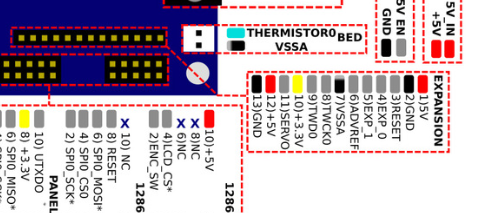
Duet 2 Maestro BLTouch Wiring
-
No, but you can connect both ground pins of the bltouch to the ground pin on the Z probe connector.
-
Awesome, thanks! I think this would be valuable information for the wiki - there's not enough there on how to set up the bltouch with the Maestro. I'm still new to the Duet boards and quite a ways off from getting mine running else I'd add some content there
-
-
@cabal2000 Almost, I installed mine yesterday:
Black/brown - ground
Red - 5Volt
Orange - Z_PROBE_MOD
White - Z_PROBE_IN -
@genghisnico13 Thanks brother. Ordered a BLtouch yesterday. Been trying to configure a Orion Piezo for the past week in which I have given up on it, Plan B=BLTouch!!!
-
I have updated the instructions for connecting a BLTouch on the wiki.
-
@dc42
This is what I have in the config.g for ES and Z-Probe
; Endstops
M574 X1 Y1 S0 ; Set active low endstops; Z-Probe
M574 Z1 S2 ; Set endstops controlled by probe
M307 H3 A-1 C-1 D-1 ; Disable heater on PWM channel for BLTouch
M558 P9 H5 F100 T2000 ; Set Z probe type to bltouch and the dive height + speeds
G31 X0 Y0 Z0 P25 ; Set Z probe trigger value, offset and trigger height
M557 X15:285 Y15:285 S20 ; Define mesh gridWiring
Red-5volt
Orange Z_Probe_MOD
Black and Brown- Ground
White - Z_PROBE_INRed light on the BL-Touch just keeps blinking and does nothing.
-
NEVERMIND!!!1
Got that figured out but now I am getting a "Error: Invalid servo index 3 in M280 command" error when i try a test -
@dc42 Is there a PINOUT diagram for the Maestro? I am thinking my issue is I have the wrong pin set in the config files
-
https://duet3d.dozuki.com/Wiki/Duet_2_Maestro_Wiring_Diagram
Use pin 64 (P64) in the M280 commands, and don't use I1. You don't need to use M307 to disable a heater.
-
@dc42
Thanks DC42. That did the trick. Was getting tired when I was reading up on it all. Very VERY new to duet boards, was using Ramps before this and had that pretty much figured out when I switched over. Maybe its time to start a Maestro only Wiki?? -
A separate Maestro-only wiki would involve a lot of duplication because so many things are the same as for the other Duets. I updated the section on connecting and configuring a BLTouch to cover the Maestro immediately after I posted my previous reply.
-
@dc42 I can't figure out where the heck the GPIO pins are in the wiring diagram for the maestro. Help!
-
@gnydick GPIO for what?There is a small Expansion header:

But the Maestro has less expand ability than the other Duet 2s.
-
@t3p3tony I want to hook up LED lights, and I just need a signal pin and ground. I found all of the charts on the wiki, but mapping them to what's in the diagram isn't straight forward. I thought I had figured it all out, but after hooking everything up, nothing happened.I used TWD0/PA3 as logical pin 62. That was after pulling up two web pages side by side to map the wiring diagram to the "using servo, etc." page, to then map to the pinout page. There really should be a mapping of logical pin numbers to exact physical pin on the board.
-
I have added expansion pin names to the table at https://duet3d.dozuki.com/Wiki/Using_servos_and_controlling_unused_IO_pins?#Section_Duet_2_Maestro. It should be able to use the TWD0 pin as GPIO provided that you never issue a M260 or M261 command. Sending either of those commands will configure the pin for I2C, making it unavailable as GPIO.
-
@dc42 Thanks. The names were very close on the other document, but not exact. This helps greatly! CC: @Shep
-
Having an issue now where the BLTouch works fine during G29 S0 bed mesh, but only deploys about half the time when using G30 S-1. Even sometimes right after starting up the machine and homing is done, I run G1 X150 Y150 Z50 and then G30 S-1 and it only deploys about half the time.
This is being used on a printer that has an endstop at Z max and I'm using the BLTouch for Z0 and bed mesh.
In config.g
M574 X2 Y2 Z2 S0
M558 P9 H5 F250 T5000
G31 P25 X-52 Y30 Z1.5
M557 X0:310 Y35:330 S40In deployprobe.g
M280 P64 S10In retractprobe.g
M280 P64 S90 -
@kenny66 Try this to see if the problem with dropping the pin is mechanical. Send the servo command to have the probe enter test mode where it just repeatedly deploys and retracts the probe. Let it do that for 15 minutes or so and try and keep an eye on it or at least listen for it. If the pin is getting stuck for some reason eventually it will get stuck while doing this test.
It's not a bad idea to take the pin out of the probe body by removing the set screw at the top and checking everything to see if it's dirty or damaged. Clean it with some soap and water and isopropyl alcohol and reassemble it.
The next culprit would be an intermittently failing wire that could be breaking connection when the print head is moving.
-
I've checked those things but the pin drops and retracts fine during a G29 S0 bed mesh. (64 probe points) The only time it's intermittent is doing a G30 S-1. It's really weird.