Pressure advance input from instrument measurement
-
This post is an input for discussion.
I have done some measurements in an instrument I built. It will measure the force on a 1.75mm filament entering an E3Dv6 with a 0.4mm nozzle. I use a Bondtech to feed the filament. The filament used is ColorFab Ngen. To make it easier to understand the result (for me) I use the ratio between 1.75 an 0.4 to express the extrusion speed. The plastic is extruded into open air, so no back pressure.
Equipment used

The graph below shows the force for different temperatures (210C to 260C). Note that the force doesn't converge on origo. For higher extrusion speeds the curves would probably be less linear.

When the extrusion stops slowly there is a remaining force that almost always is around 1N. It is possible that this force is caused by the friction between the hot, semi melted filament and the nozzle and lower part of the heat break. I the force is subtracted from the earlier graph it looks like the graph below. For the higher temperatures the curves now can be extrapolated to origo.

It is also possible to to measure the enthalpy for melting the plastic as shown below.

And the total power used, graph below.

The first graph can also be plotted in an other way and will then show, for a given print speed, how the force decreases with increasing temperature.

I have some thoughts regarding Pressure Advance
- If there is a remaining force of 1N the trapped volume between the nozzle tip and the non sliding section of the filament would heat up, expand and ooze out.
- Is Pressure Advance (M572) and non-linear extrusion(M592) overlapping.
- These measurements are steady state measurements. Do they confirm the theory behind Pressure Advance?
Any other comments?
-
Nice work.
@urban said in Pressure advance input from instrument measurement:
It is possible that this force is caused by the friction between the hot, semi melted filament and the nozzle and lower part of the heat break.
Indeed, a large part of the force needed to extrude is sliding the plug that forms to seal the inward side of the extruder's barrel, particularly with materials like PLA with a low glass transition. If you push the filament by hand you will notice it hard to move at first but then it gets easier once it is moving because the plug gets shorter.
Tapering the inside of the barrel where the transition happens acts like a mould relief taper for the plug and reduces the force needed to extrude by a factor of about three in my experiments. I don't know if any commercial hot ends have such a taper.
@urban said in Pressure advance input from instrument measurement:
These measurements are steady state measurements. Do they confirm the theory behind Pressure Advance?
Pressure advance is about compensating for the springiness in the system, so steady state measurements won't show it. Imagine a perfect stepper motor coupled to the extruder with a spring. As the flow rate increases the pressure increases, which compresses the spring meaning the filament doesn't move quite as far as it should. To compensate the motor needs to spin a little faster and further.
-
Nice work!
Pressure advance assumes that the extrusion system exhibits elasticity such that there is a compression that is proportional to extrusion rate. Your measurements show that the additional force needed is proportional to extrusion rate. Therefore, if the system behaves as a linear spring (compression proportional to force), then the pressure advance algorithm is correct.
The elasticity is made up of the compressibility of the filament in the Bowden tube, the stretchiness of the Bowden tube, and the motor elasticity. We can calculate the motor elasticity. Therefore, from your measurements we can calculate the minimum pressure advance needed, which should be close to the actual value needed in a direct drive extruder. the
Duet WiFi hardware designer and firmware engineer
Please do not ask me for Duet support via PM or email, use the forum
http://www.escher3d.com, https://miscsolutions.wordpress.com -
Wonderful work!!!!!!
That is a good work for a scientific/engineering paper!
How about measure dynamically. From a slow speed, then a sequence of steps.
It is a simple, static, measurement that could also show extruder/filaments issues that we use the laser sensor today. It is brilliant

I bet that if I use a spring mechanism then read the displacement using my laser sensor I could also measure force.
-
@dc42 With a small nozzle most of the force is proportional to flow rate but with a larger one, i.e., 0.6mm it is possible to get the force reduce as you increase speed due to the plug at the transition dominating.
There it also the secondary effect that extruding faster means the plastic is cooler as it flows through the nozzle as it has has less time to heat. Less noticeable with hot ends with a large melt zone.
It would be great to be able to measure the pressure at the nozzle. Large commercial extruders manage to do that somehow.
-
@nophead said in Pressure advance input from instrument measurement:
Large commercial extruders manage to do that somehow
Could something like this work? I dread to think what it costs with the amplifier, readout, etc.
-
@adavidm Or this one, for temp and pressure:
-
@adavidm The sensors you link to has a temperature limit off around 200C due to the fact that they are based on silicon. For higher temperatures GaNi (Gallium Nitride - also used for LED's) sensors would increase the temperature, but a few years ago (hmm... maybe ten years ago) they where only on research level. For some injection moulding machines Mercury is used to carry the pressure to a colder place where they can be measured with the sensors like the ones you linked to.
-
@urban how do they account for the relatively large expansion of the mercury due to the heat?
I was thinking of perhaps a stiff diaphragm with a plate near to it to form a variable capacitor. The second plate could be attached to something cold with air in between, so nothing to expand with the heat.
-
@dc42 As I understand it Pressure Advance is a linear compensation.
- From the first curve one can see that for high temperatures the curve will go through origo. For lower temperatures there would be an offset. Shouldn't Pressure Advance have the form
a+bx? - They are also temperature dependent. Then there need to be a temperature component in the formula as well. I have found that a Bi-Cubic formula can approximate this fairly well.
The formula
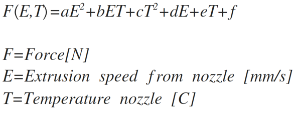
The graph where the doted lines are from the formula and the solid lines from measurement

- From the first curve one can see that for high temperatures the curve will go through origo. For lower temperatures there would be an offset. Shouldn't Pressure Advance have the form
-
@nophead I don't know how thermal expansion is handled, but I suspect it is water cooled. My work was with the GaNi sensors.
-
@brunofporto I have done some dynamic measurements, mostly with the intent to study retract.

The graph shows three repeated tests. I don't remember the exact settings.
- The graph starts with an S-curve type acceleration. The hotted was primed a few minutes before the test.
- The force build up to close to 8N initially
- The force is reduced once everything gets going
- The retract takes place and the force is reduced to -1 N. This is the holding force and independent of how much you retract it will not be lower. I think this is caused by plastic deformation of warm filament near the heat break. 1N is the force you get for all filaments I have tested.
- The plastic deformation relaxes the force to zero in less than a second.
- The force build quickly after the un-retract when the retract state have been for one second. The un-retract length was the same as the retract length.
The waviness you can see in curves from 4-10s (peak to peak around 1 s) are caused by the gears in the planetary gear used in the extruder.
The very smal jitter in the curve is the full steps of the stepper. I use a Trinamic with 16 micro steps and interpolation to 256 micro steps.
-
Great info on nozzle pressure vs temperature and feed rate. So at 250'C you can feed almost 5x as fast as at 210'C for the same nozzle pressure (with your configuration of course)!
On your dynamic graph, a correctly set pressure advance constant will shift the linear rising pressure slope, but won't cure the post-rise excess pressure overshoot I don't think. For that, a different algorithm would be needed.
-
@urban The ripple due to gearing is a shock. I thought involute gears are supposed to be constant velocity. I have often wondered if a timing belt drive would be better as it has less backlash and probably more constant velocity.
-
@nophead said in Pressure advance input from instrument measurement:
.........................
It would be great to be able to measure the pressure at the nozzle. ..................This is something that I have given a lot of thought to over the years. One way would be to use a Diamond hot end but only feed filaments into two of the inputs and fit a transducer into the third input. Sadly, I don't have the resources (financial or otherwise) to pursue this.
-
@deckingman I think the main problem is the price of the pressure sensor that can handle that temperature. It renders this method, of measuring pushing force right at the hotend, a very nice approach!
It is measuring pressure after all, with a little friction but... it just needs to correlate with the nozzle area
-
@brunofporto said in Pressure advance input from instrument measurement:
@deckingman I think the main problem is the price of the pressure sensor that can handle that temperature. ..............................................
Yes, absolutely. Many years ago, I worked for an engineering consultancy and we were measuring pressures in real time inside the combustion chambers of internal combustion engines. I think I'd have to sell my house to buy the equipment we were using.

-
@brunofporto The problem is it isn't a little friction. I can easily dominate the force with PLA because it is not very viscous but it is very rubbery past its glass transition and creates a lot of friction like a tyre.
If we could measure the pressure in the melt chamber accurately and in real time we could create a servo loop.
-
@nophead Sure - a nice masters or phd thesis to go for
-
@adavidm the sensor you linked could work for this application in an appropriately modified hotend:
https://www.kistler.com/?type=669&fid=75071&model=document
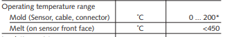
Sensor face exposed to the molten plastic @ <450C but the remainder insulated from the heater block. Only practical for testing but still it could be an option.