Controlling a Cetus3D with Duet3D 0.8.5
-
Hi
I am trying to use a Duet3D to control a Cetus3D, I mean why not?
")
I have mounted a micro switch as endstop for the bed and an Ormerod Hot End Board V2 (dual nozzle) for homing Y and Z-axis.
I can home all axis and it seems to work ok, but it is nothing but smooth. Especially lowering Z during homing.
Here's a short clip of homing : [https://www.youtube.com/watch?v=GIkJKHXSbOc](link url)Could the wiring be wring be wrong? The order of the wires are the same on the motors as on the board.
I have played around with settings but other than steps/mm I have not noticed any improvements (or changes).
Lower acceleration, less speed, more amps...
These are my settings:
M92 X80.00 Y80.00 Z80.00 E420.00 ; Set steps per mm
M566 X90.00 Y90.00 Z90.00 E120.00 ; Set maximum instantaneous speed changes (mm/min)
M203 X30000.00 Y6000.00 Z500.00 E1200.00 ; Set maximum speeds (mm/min)
M201 X100.00 Y100.00 Z100.00 E250.00 ; Set accelerations (mm/s^2)
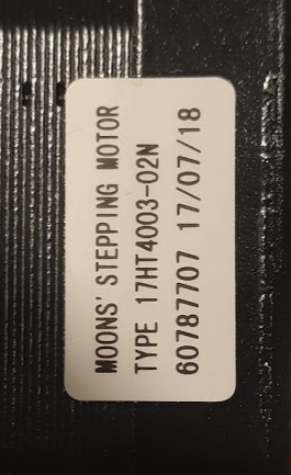
M906 X1200.00 Y1200.00 Z1200.00 E800.00 I30 ; Set motor currents (mA) and motor idle factorLabel on Z-stepper motor, if it helps.
Please advice
/Tomas
-
 @fotomas said in Controlling a Cetus3D with Duet3D 0.8.5:
I am trying to use a Duet3D to control a Cetus3D, I mean why not?
I have mounted a micro switch as endstop for the bed and an Ormerod Hot End Board V2 (dual nozzle) for homing Y and Z-axis.
I can home all axis and it seems to work ok, but it is nothing but smooth. Especially lowering Z during homing.
Here's a short clip of homing : [https://www.youtube.com/watch?v=GIkJKHXSbOc](link url)
Could the wiring be wring be wrong? The order of the wires are the same on the motors as on the board.
I have played around with settings but other than steps/mm I have not noticed any improvements (or changes).
Lower acceleration, less speed, more amps...Cetu3d's original stepper motor are 12v, and the Duet must be powered at 24v to avoid any noise from the motor steppers.

This is mine Cetus3D,to power at 12v, I had to replace all the steper motors.

-
@flopo76 said in Controlling a Cetus3D with Duet3D 0.8.5:
Cetu3d's original stepper motor are 12v,
They is no such thing like 12V stepper motors, stepper motors are current driven so it doesn't meter with voltage are you driving them (even 48V would hurt them, but doesn't Duet doesn't handle such high voltage).
And BTW, on the photos this isn't Duet 0.8.5 but Duet2 -
@fotomas, I suspect you have the current set much too high for those motors in the M906 command, which will have the effect of making them behave as if you are sending them full steps. I wasn't able to find any data for that motor, but if the phase voltage is 12V then 400mA current may be about right; but you will need 24V power to drive the motors smoothly.
You can get an estimate of the motor rated current by measuring the resistance of one phase and the length of the motor, and then searching a stepper motor catalog (e.g. omc-stepperonline.com) for motors of similar size and phase resistance.
-
@dragonn On my Cetus3d with original steppers and wifi duet, powered at 12v it made a lot of noise and vibration.Instead with the original main board powered at 19v, no vibrations and noises.The original steppers of Cetus are at 38ohm per phase.Then I mounted motors with 3.4 ohms per phase and no longer feels when it works.At 38 ohms per phase, to make no noise the steppers must be set to 0.34A, but my hotend is very heavy and z axis was not up. I know that my printer is with Duet wifi and his with Duet 0.8.5
Sorry for my English.
-
Thank you for the help, issue solved.
Now it moves much smoother. Lowering the mA on the stepper motors was the trick.
Moving Z-axis down make a bit of a chunky sound and that is the friction based contraption that prevents the Z-axis from falling when powering off. Moving Z-axis upwards is as smooth as the other axis.
Time will tell if this will be a problem during print, especially if lifting Z during transportation moves. Otherwise moving Z downwards during prints don't happen (I think?)
Here's a video of homing with a setting of about 350 mA and voltage of 18v. After homing Z is moved 50 mm upwards, to show that Z+ moves as smooth as X & Y.
[https://youtu.be/SXkN2tT7tvY](link url)
-
I see you are using one of my Ormerod hot end boards!
The Y axis is still much noisier than I expect from a Duet.
Duet WiFi hardware designer and firmware engineer
Please do not ask me for Duet support via PM or email, use the forum
http://www.escher3d.com, https://miscsolutions.wordpress.com -
@dc42 Yep, I needed as sensor and since my Ormerod has been collecting dust since I got the Cetus I borrowed the hot end board. One of my "goals" with this conversion of the Cetus is to make it reversible so I haven't bothered wiring up all the other features of the hot end board. I do have some wires unused in the TP-cable i scavenged for the hot end board so maybe some lightning would be nice.
As of now I am running the duet from a Lab-powersource so I can crank up the voltage to 24. But my goal was to use the Cetus powerbrick which is at 18V.
-
I have happily been printing for a few days, tinkering with settings, fans, PanelDue etc.
It was when I printed a part I designed for the printer I realized that my part come out mirrored. First asymetric print
I thought this was an easy fix but I can to seem to ge my head around it. 
So can anyone please help. What do I do to reverse my Y-axis to go the other way?
I have tried to revere the stepper motor with M569 P1 S1 => M569 P1 S0, that works but I haven't been able to get all the other parts in order. I Changed the M574 Y1 Z1 S2 => M574 Z1 Y2 S1, to no apparent effect.... I reversed the connector on going in to the duet and then reversed it back in config (I guess that it cancels out each other)
I have tried som many things I am not sure what I have done or in which order. So an explanation on how all this ties together would be much appreciated.
Is there more to it than using M569, M574 and coordinates in homing files?
This is the config I had before trying to fix this, all is well except mirrored Y-axis.
;Drives
M569 P0 S1                               ; Drive 0 goes forwards
M569 P1 S0                               ; Drive 1 goes backwards (Y-axis)
M569 P2 S1                               ; Drive 2 goes forwards
M569 P3 S1                               ; Drive 3 goes forwards
'''
;M92 X80.00 Y80.00 Z80.00 E118.00
M566 X90.00 Y90.00 Z90.00 E120.00
M203 X18000.00 Y18000.00 Z10000.00 E5000.00
M201 X150.00 Y150.00 Z100.00 E250.00
M906 X340.00 Y340.00 Z500.00 E400.00 I30
M84 S30

; Axis Limits
M208 X0 Y0 Z0 S1
M208 X180 Y180 Z180 S0

; Endstops
M574 X1 S0

; Z-Probe
M574 Y2 Z1 S2
M558 P1 H5 F250 T6000
G31 P538 X0 Y0 Z3.65
M557 X55:180 Y15:180 S20
-
@fotomas said in Controlling a Cetus3D with Duet3D 0.8.5:
Is there more to it than using M569, M574 and coordinates in homing files?
To reverse the direction of the Y axis you also need to adjust M569, M574, and in homey.g and homeall.g reverse the directions of the Y homing moves and any Y homing stop backoff moves. See https://duet3d.dozuki.com/Wiki/ConfiguringRepRapFirmwareCartesianPrinter#Section_Homing_X_and_Y and https://duet3d.dozuki.com/Wiki/ConfiguringRepRapFirmwareCartesianPrinter#Section_The_homeall_g_file.
-
After a night sleep and some distance to the whole thing I sorted it out. I had almost right, the one thing that threw me of was one line I had added in homeall.g G92 X-3 Y-5. It was just an adjustment since my Y-axis home outside the printable area. But it surley messed things up
dc42 Thank you for your quick reply, now I am on the right track again.
Oh, and this is the piece I drew to print verifying that the axis are in right order. It was after the print finished it dawned on me both letter X and Y can be mirrored, without showing. Bad luck when thinking, I guess
-
HI,
I'm considering doing the same, swapping out the default electronics with a Duet. I intend to use the sensorless homing feature, but I am not sure if that will work for the Z axis. For the Z-axis I still got three difference Z-axis sensors, the original three wire ormerod sensors, the 4 wire one, and the DC42 sensorboard with ultrasonic sensor. Am I right assuming you're using the latter as sensor? Or did you try sensorless home for that one as well?
And how may steps per mm did you configure for the extruder? -
@onno
I am using the earliest sensor made by dc42, dor an Ormerod with dual extruders. Link. I use it to home Z and Y axis, for the X axis I have mounted a micro switch besede the x-axis stepper motor.I will post the STL's for the sensor board, micro switch, power inlet and casing, if anyone is interested.
My config for the cetus looks like this, note the quite exotic heater values, but hey the work and have beed calibrated pretty well. I am using the cetus almost as delivered. 18v powerbrick, same extruder, same stepper motors. And tuned in it works very well, both with PLA and TPU, on original table without raft.
I am happy to answer any question you may have.
; General preferences G90 ; Send absolute coordinates... M83 ; ...but relative extruder moves ; Network M550 PCEDUT ; Set machine name Cetus + Duet => cedut ;) M551 Preprap ; Set password M552 P192.168.0.65 S1 ; Enable network and set IP address M553 P255.255.255.0 ; Set netmask M554 P192.168.0.1 ; Set gateway M586 P0 S1 ; Enable HTTP M586 P1 S0 ; Disable FTP M586 P2 S0 ; Disable Telnet ; Drives M569 P0 S1 ; Drive 0 goes forwards M569 P1 S1 ; Drive 1 goes backwards (Y) M569 P2 S1 ; Drive 2 goes forwards M569 P3 S1 ; Drive 3 goes forwards M92 X79.72 Y79.72 Z79.72 E118.00 ; Set steps per mm; used to be E127 M566 X230.00 Y230.00 Z90.00 E120.00 ; Set maximum instantaneous speed changes (mm/min) M203 X28000.00 Y28000.00 Z15000.00 E10000.00 ; Set maximum speeds (mm/min) M201 X200.00 Y200.00 Z100.00 E250.00 ; Set accelerations (mm/s^2) M906 X340.00 Y340.00 Z500.00 E500.00 I30 ; Set motor currents (mA) and motor idle factor in per cent M84 S30 ; Set idle timeout ; Axis Limits M208 X-10 Y0 Z0 S1 ; Set axis minima M208 X185 Y184 Z180 S0 ; Set axis maxima ; Endstops M574 X1 S0 ; Set active high endstops ; Z-Probe M574 Y2 Z1 S2 ; Set endstops controlled by probe M558 P1 H5 F250 T6000 ; Set Z probe type to unmodulated and the dive height + speeds G31 P538 X0 Y0 Z3.82 ; Set Z probe trigger value, offset and trigger height M557 X50:180 Y10:165 S40 ; Define mesh grid G29 S1 ; Load stored mesh grid from SD Card ; Heaters M140 H-1 ; Disable heated bed M305 P1 R4700 T112 B-425 C7.060000e-8 ; post multimeter measurement M143 H1 S280 ; Set temperature limit for heater 1 to 280C ; Fans M106 P0 T50 H1 ; Thermostatic control is on, turn on at 50cC ; Tools M563 P0 D0 H1 ; Define tool 0 G10 P0 X0 Y0 Z0 ; Set tool 0 axis offsets G10 P0 R0 S0 ; Set initial tool 0 active and standby temperatures to 0C ; Pressure advance M572 D0 S0.05 -
Thanks for the info, this provides a great starting point once I get the Duet in (still need to order it).
Right now the printer is still too busy to take it out, but like you, I'm trying to stay close to the original Cetus initially, although I foresee switching to an E3D Titan Aero at a later stage as well, along with 0.9deg steppers, and a heated bed.
Once again, thanks! -
@fotomas Thanks a lot for helpful infos. I’m getting Cetus MK3, which should arrive next month, and joined Cetus Duet club
How you connect Cetus powerbrick to Duet? Any modification needed?
Cookie
-
@cookie
I took a DC jack from an old DELL laptop docking station. 3D Printed a holder so I could screw it down to the Cetus bottom plate using an already existing hole.The Cetus bottom plate has four holes for the original controller board. Two of them fits the Duet 0.8.5 board as is. The 3D printed part for the DC jack reaches in underneath the the Duet offering support.

-
@fotomas great! Any photo of this dc jack? So I can google it and try to get one.
-
@cookie
I de-soldered one like in the pic below. But an Ebay or google search for "DC Jack female 7.4 mm" give you some other options.
-
Hi,
Another Cetus MK3 owner here. Just got my Duet Wifi, but of course don't want to start pulling cables and boards out of a working printer before I know I have everything and it's reasonably likely to work.
I think I'm going to need at least a different power supply (not a problem, I'll bring over a bench supply tomorrow). But is that probably it?
I'd also be super grateful if someone in the know, could post the high level overview of the process? I mean like what are the chapter titles; then I can go off and bang my head against figuring out the finer details of all that until it works..
Thanks

Dan -
dsmudger
I would say these are major steps
- Homing switches (I use a microswitch for X and an old dc42 IR sensor for Z and Y)
- Make adapters or get new cables to stepper motors
- Make adapter or new cable for hot end
- Power supply (I am using the original Cetus power supply)
- Configure the Duet3d (steps/mm and heater values you can see above, the rest I think may vary in your case)
Original connectors can be forced into the Duet board, but I ended up making adapters both for the steppers and the hot end. Pictures below show before the adapters during "proof of concept phase". On the hotend it self I made a new board using experimental circuit board and matching connectors. There was too much interference in the ribbon cable for the signal from the IR board so I added an ethernet (twisted pair) cable for that.
If there are any questions I would be happy to help.


